updated 26/11/2013
|
|
updated 26/11/2013 |
|
 |
 |
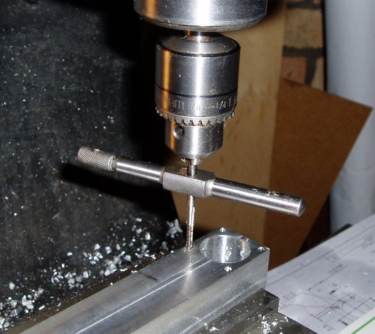 Tapping the holes |
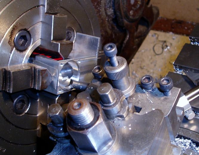 Boring the case |
 Turning the chamfer |
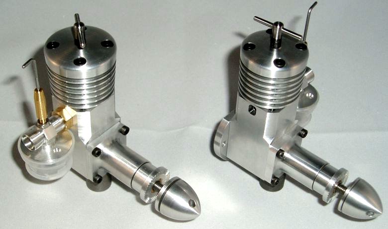
 The finished case |
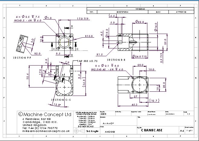 The drawing |
 |
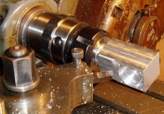
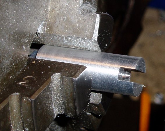
The first is to hold the end of the flat rod blank in the lathe for turning the shank. I didn't fancy fiddling about with a 4 jaw chuck so I made a simple jig that acted as a back centre and also drove the rotation. This has worked very well and I did all the turning of the 5 rods in less than 30mins. | 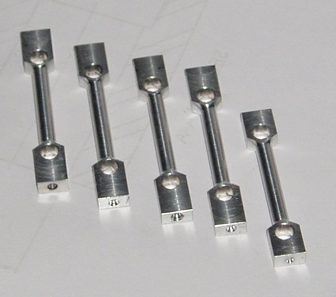 | >
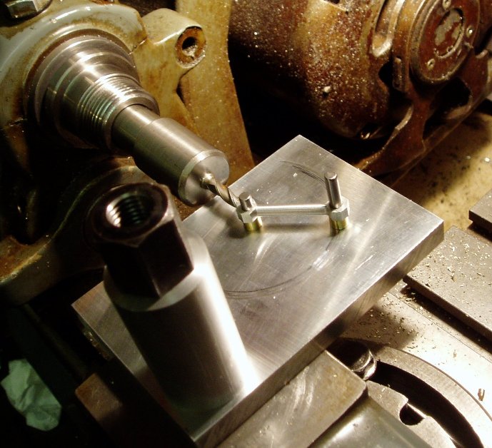 |
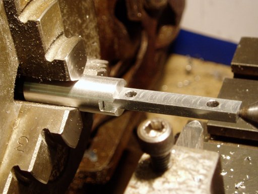
To machine the end rads I first removed some of the extra material in the milling machine then I had a bit of a think on how to do the milling of the radius. I like the method described by Ron Chernich to make the replacement rod for the Taipan 66 but I thought that I could make it even easier. I decided to use my trusty ML7 and work with the rod horizontal and I though that it would be easier to see what was happening. I already had a set of N0. 2 Morse taper milling cutter holders from when the lathe was my only milling tool and I thought that it would be even easier to control the rod if it was flat on a plate and I could look from above. I also found that by using a pin and spacer at the holding end I could ensure that the rod stayed parallel to the plate and it was very easy to control. Another thing I found was that, if I set the horizontal centreline of the rod end about 1mm off center so that the cutter was mainly cutting with the down moving teeth, the rod stayed down and wasn't lifted up by the cutting forces. A secondary benefit was that the cutting could be easily seen where it blended into the radius of the shank. Of course this was possible only if the rod was turned over to do the second side. This has all worked well and I improvised a stop which made the cutting repeatable - I will update the jig to add this to the design. Different thicknesses of rod will need different spacers but these are easy to make. |
© 2010 Mike Nelson