 |
Recreating LYN
Progress log
updated see page 2 |
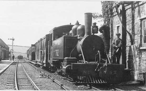 |
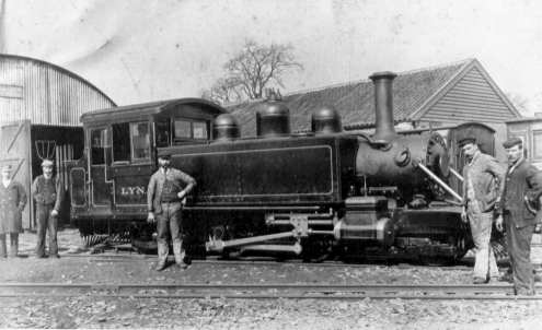
I have been contracted by The 762 Club to work with Ian Gaylor to produce the working drawings required to recreate this Baldwin Locomotive.
The version of the loco that we are creating is the later version after its rebuild by Southern as shown on the right in the heading photos. The plan is to create loco in a "looks like, works much better" version incoporating a number of the improvements in steam loco design that have happened since the original was cutup. Amongst the "improvements" will be :-
a superheater, Increased boiler pressure, rolling bearings, a "gas producer" coal firing design, reduced friction valve design.
These changes will produce a loco that is much more efficient, uses less fuel, makes less smoke, doesn't throw sparks up the chimney, uses less water, pulls more weight but still recaptures the look and feel of the original loco.
For more info on the gas producer firing system as used on the kirklees Light Railway go here
and
here
for a good description on how it was applied to existing locos.
I plan to keep this page as a log of my progress. I am using a 3D CAD package to produce a 3D model of each of the parts prior to creating the drawing of the part in order to ensure that the potential for errors to creep in is significantly reduced.
The weblog now runs to 4 pages:-
Currently I am producing a 3D model of the boiler. This is not the documentation that will be used, as the boiler manufacturer, Bennett Boilers, will produce their own documentation and be responsible for the delivery of a working boiler. The boiler is the core of the locomotive and this model will be a huge help in ensuring that the rest of the assemblies fit and work as expected. Click on any of the images for a full size version.
Modelling progress up to 18th Feb 2011
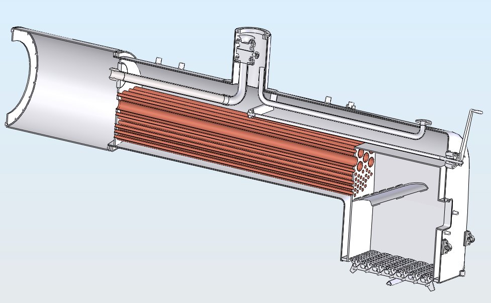
Section through boiler 18th Feb 2011 |
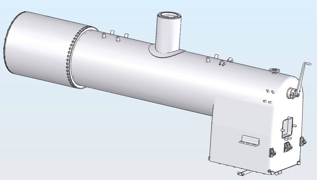
View of boiler 18th Feb 2011 |
Close up of firebox area 18th Feb 2011 |
Modelling progress up to 28th Feb 2011
All the currently modelled bits put together. The frames are modelled from the original drawings and will be subject to changes to make them acceptable to the modern standards. The cab is now finished ready for installation |
Current work is to model the cowcatcher - a much trickier modelling exercise than it looks |
Modelling progress up to 8th March 2011
Well, I have been working on the boiler cladding and I guess that I am half way through the modelling. The Firebox backhead cladding was a real challange and the model is still reporting a problem(et) but I know what the problem is and I think that I may be able to force the program to model it correctly with a bit of cunning!
This is the latest jpg of the loco complete with the cladding |
The firebox backhead has has to be modelled using the sheetmetal tools so that the flat pattern can be created easily ready for lasercutting before bending. |
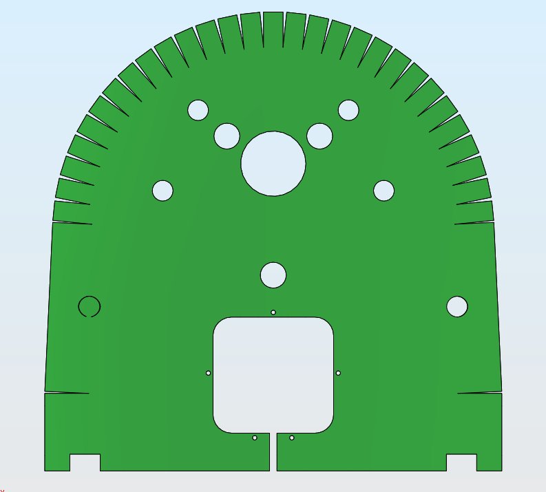
The firebox backhead cladding flat pattern for lasercutting. |
Modelling progress up to 11th March 2011
The boiler cladding is now broadly finished. The backhead cladding model is now OK with no errors and I have done the detail drawing and a DXF file for it to be lasercut. The cladding clamping straps are modelled. I have added the sand domes, only a rough guess at present but I will firm them up when we have decided how to make them and have the final dimensions to hand.
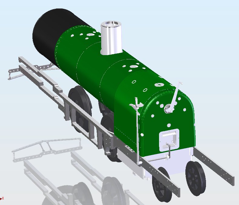
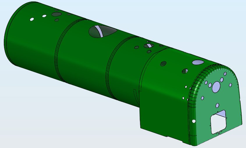
This is the latest jpg of the loco with the cladding finished and the temporary sand domes in place. |
The cladding is now modelled and the detailing of the parts has started. |
detail of the clamping straps for the boiler cladding. |
This is probably as far as I can go for a while as there are some decisions that need to be made before we start some of the other elements.
Modelling progress up to 12th April 2011
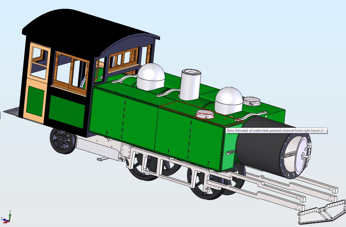
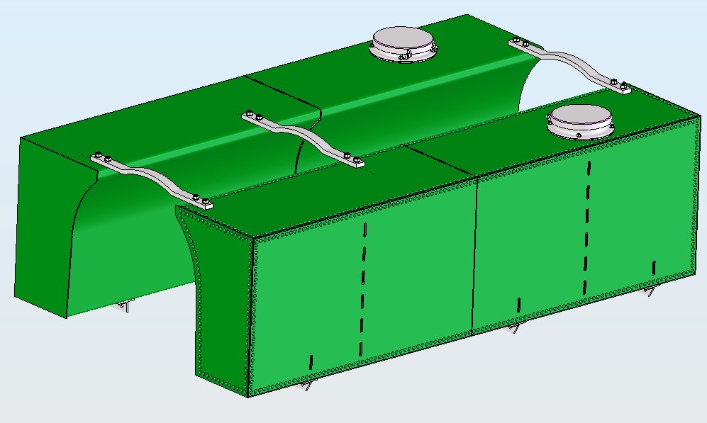
I have been getting on with the water tank modelling. Ian has provided an outline design and I have been filling it out into a 3D model. I quess I am about 3/4 of the way through. I have been doing the drawings as I go along so I am close to being able to issue all the tank drawings for quotation. We won't release any for manufacture until some of the other areas have been modelled so that I can be sure that it will all fit.
Modelling progress up to 11th May 2011
The water tank is now modelled and the drawings are ready for issuing for quotation. I have also finished the drawings of the smokebox and smokebox door ready for quotation.
The firebox door has been redesigned to better reflect the shape of the original round door although this does compromise the efficiency of the gas producer firing system somewhat. We have tried to provide the capability for controlling the drawing in of air above the fire in the door assembly rather than the original idea of controlling the opening of the door with a lever and foot pedal. The new design is fully modelled but I will wait to detail it until after our design review meeting at the end of the month.
The cladding is in the process of being detailed and should be finished ready for quotation this month. There may be a few changes as we havent sourced the boiler water gauges and the positions of the mounting holes for these will need to be incorporated
The sand domes are partially designed and the internal sand containment and delivery parts are being modelled.

This is the latest design of the firebox door in the closed position the door is opened with the handle shown and a cam system holds it either open or closed. The small lever at the top of the door controls the air into the top of the firebox (shown in the fully open position). |
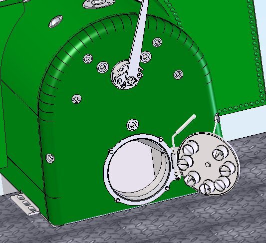
The tubes shown are to make this incoming air swirl to improve the efficiency. |

This is a cross section thro the firebox showing the main features. The deflector pushes the incoming swirling air down to mix it with the burning gas and ensure complete combustion. |
|
Modelling progress up to 26th May 2011
The super heater is now modelled and the improved boiler mounting completed. I have also updated the chassis to have the main wheel axles and cranks fitter. The steam valve and attendant parts have been up dated and are now nearer to the final design. The main effort has been to get the superheater modelled so that we can have a design review at the end of the month.
This is a complete cross section showing the current state of the model. |

This is the superheater. |
|
Modelling progress up to 3rd June 2011
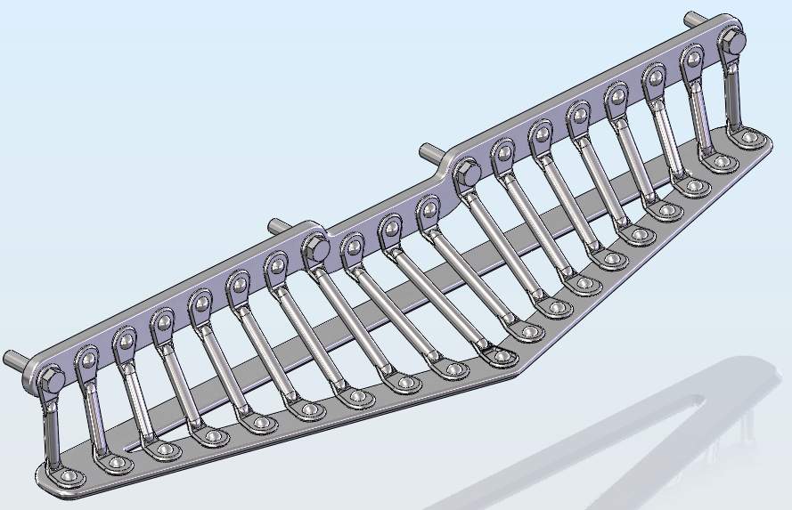
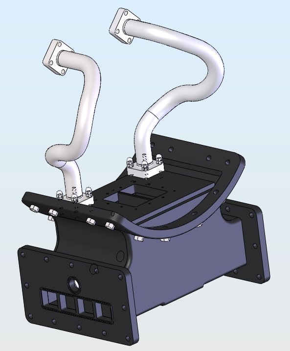
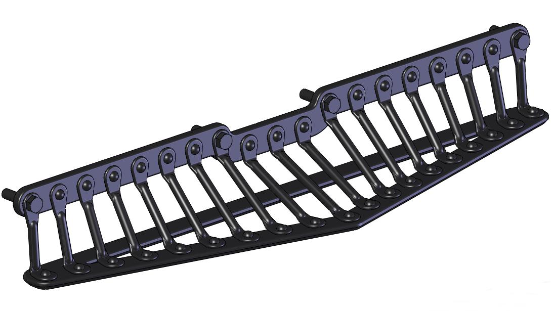
Well, we had the design review and it does look as though we are going in the right direction from a technical viewpoint. There are a few non-technical things that will be addressed over the next couple of weeks. In the meantime I have been pressing on with modelling the buffer assemblies. I won't be doing the drawings for this assembly as the plan is to purchase it finished from the Ffestiniog Railway Company as they are already having some identical items made for their own use. There is a reasonably good drawing from around 1925 when the L&B was in Southern Railway ownership and I have been able to use this to create an accurate model (see below)
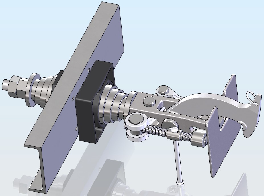
This is a complete assembly of all the components. On LYN the front assembly and the rear assembly were different. |

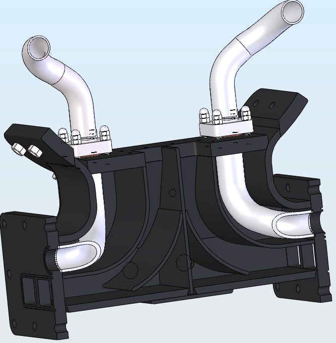
This is the buffer assembly as fitted to the front of LYN. Only the hook is fitted. In use the hook was lifted clear by a chain to protect it. |
This the assembly as fitted to the rear of LYN. The hook is not fitted but the parts for tensioning the coupling are there. |
Modelling progress up to 20th June 2011
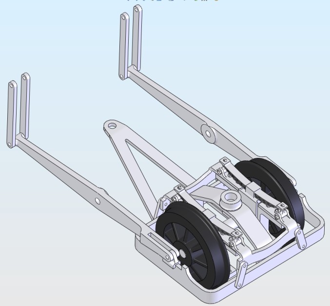
The detail drawings for the firedoor are now complete and ready for sending out for quote, The cladding drawings are complete and also ready for quotation. The cowcatcher is finished and detailed as is the smokebox. all of these are subject to changes when we check the drawings and finish other areas. I have started the design work for the pony trucks. There is very little information on the pictures and drawings that I have available but I have been much helped by Stephen Phillips, a 762 Club member and an excellent draughtsman as well as a keen L&B historian who has done a lot of research in this area and created a couple of excellent illustration of the leading and trailing trucks. The model of the trailing truck shown below is still quite speculative and will be firmed up as more info is obtained. It also has to cope with the deeper firebox that will be fitted to the loco.
The cowcatcher model shown below doesn't try to replicate the actual shapes of the forged ends as they will depend on the actual forging process and can't be modelled precisely. The drawings show only the important dimensions.
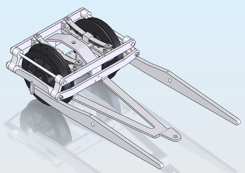
This is a picture of the current model of the trailing truck. |
The cowcatcher is now complete subject to checking. |
The firebox door is finished also subject to checking. The tubes shown are part of the gasproducer system and allow good control of the secondary air to improve combustion and reduce smoke and sparks. |
Modelling progress up to 15th July 2011
Not as much progress this month as we are waiting for the boiler order to be placed. I have offered to do the detailing of the boiler to save both time and money. I already have a nearly complete model of the boiler and will update this with input from the boilermaker. I have made a good start to the simplified (non-rocking) grate assembly and, once we have had a design review (Ian and I) I will be able to finish the modelling and do the detailing.
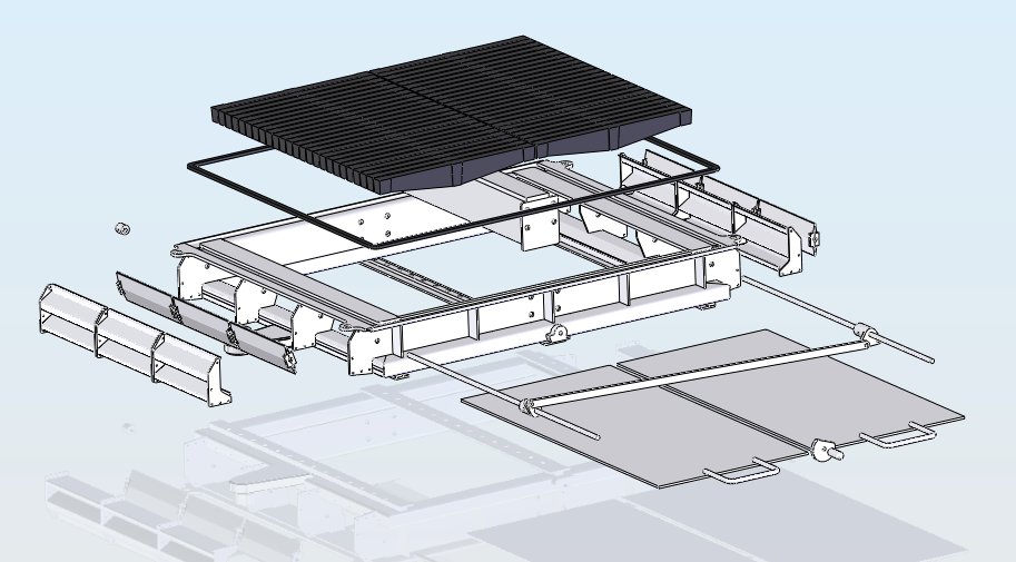
This is the current model of the ashpan exploded. |
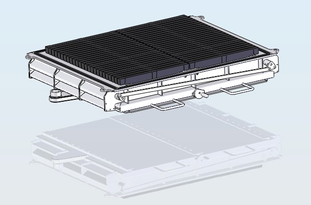
This is the current model of the ashpan. |
Modelling progress up to 20th August 2011
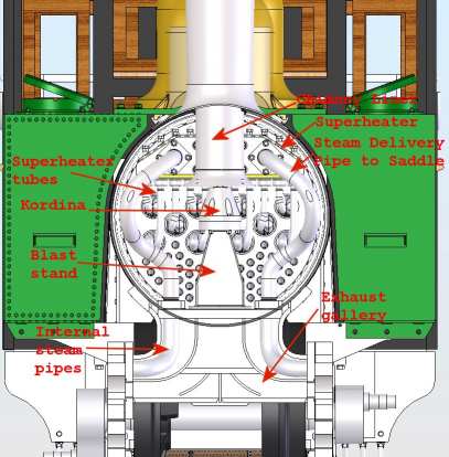
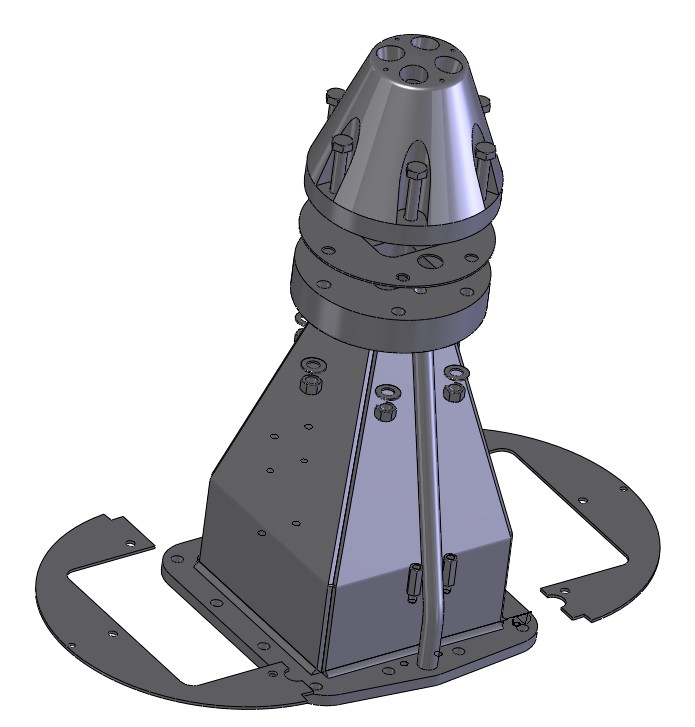
The boiler order is still to be placed but I have high hopes that a meeting in the next couple of days will get that underway. I have been working on the draughting of the engine. This is one of the more important elements that needs to be right to ensure that the engine delivers the performance required and is easy to fire and control. Ian has done the calculations and provided a sketch layout of the Lempor system. I have now done most of the detail design and am ready to start the detailing.
This design is quite interesting. The Exhaust steam from the cylinders is directed up the blast stand (the blast stand is split into 2 channels one from each cylinder) and is merged in a Kordina before being ejected through 4 carefully shaped nozzles into the chimney. This design gives the 2 main benefits of sucking the fire gasses through the boiler tubes and creating a low pressure pulse to the other cylinder thus improving the power delivery by minimising exhaust back pressure. There are some compromises to the ideal geometry because of the shape of Lyn's chimney but the result should be a much better steaming performance than would be achieved with a conventional single blast nozzle and conventional chimney.
The small supplementary steam pipe is used either to assist the draught via 4 small blower nozzles when the engine is stationary and there is no exhaust to power the Lempor or, by connecting to a compressed air source, to provide some draught when firing up the engine from cold.
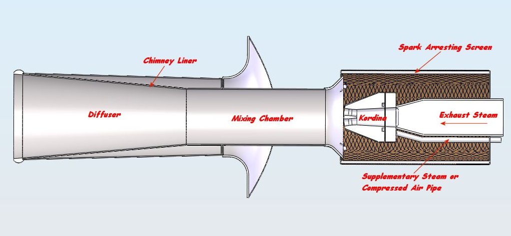
Cross section through the Chimney and Lempor assy. |
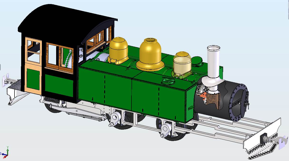
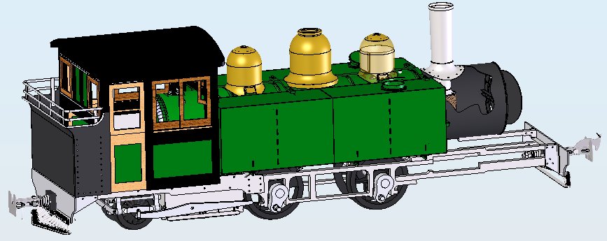
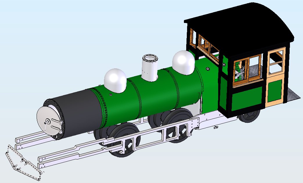
Picture of the current model of LYN. |
Modelling progress up to 3rd September 2011
We are still waiting for the boiler order to be placed but I think that it is much nearer. One thing that has been thrown up is that the plate thickness has been increased from 10mm to 12.5mm not a big change but it has had a significant impact on the 3D model of the design. The waterlegs of the boiler are now too narrow (they were already close to the minimum) and increasing these has required the boiler barrel to increase from 875mm diameter to 937 diameter. This won't change the outside dimensions of the cladding but it will mean that the insulation will be reduced. We have taken the opportunity to increase the waterlegs by more than the minimum which should give the boiler a better performance. Another change has been the change to remove the expensive formed flange curves from the boiler design and to change it to a "cut and shut" style.
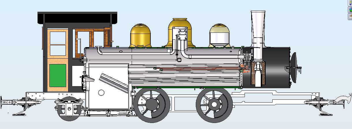
Cross section through the engine. |
Modelling progress up to 11th November 2011
The boiler order is now placed and also the build contract With Alan Keef. I have taken on the drawing of the boiler in order to reduce the cost (this is unpaid work in addition to the drawings I am contracted to create). I have started the boiler drawings and am working with the boilermaker to ensure that they are correct and able to pass the insurance requirements.
I have now completed some 296 drawings (including the first pass boiler and superheater drawings) representing some 930 parts. So you can see that LYN is progressing OK so far.
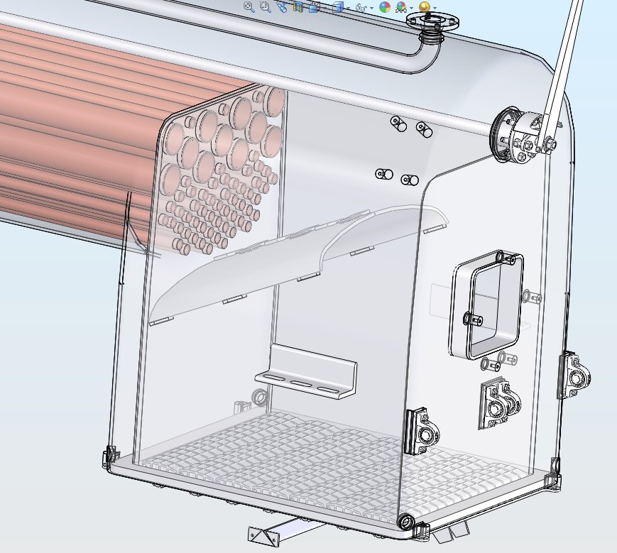
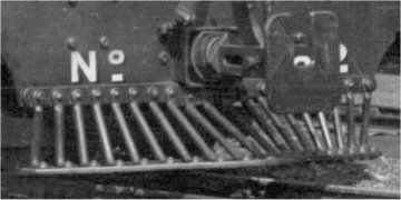
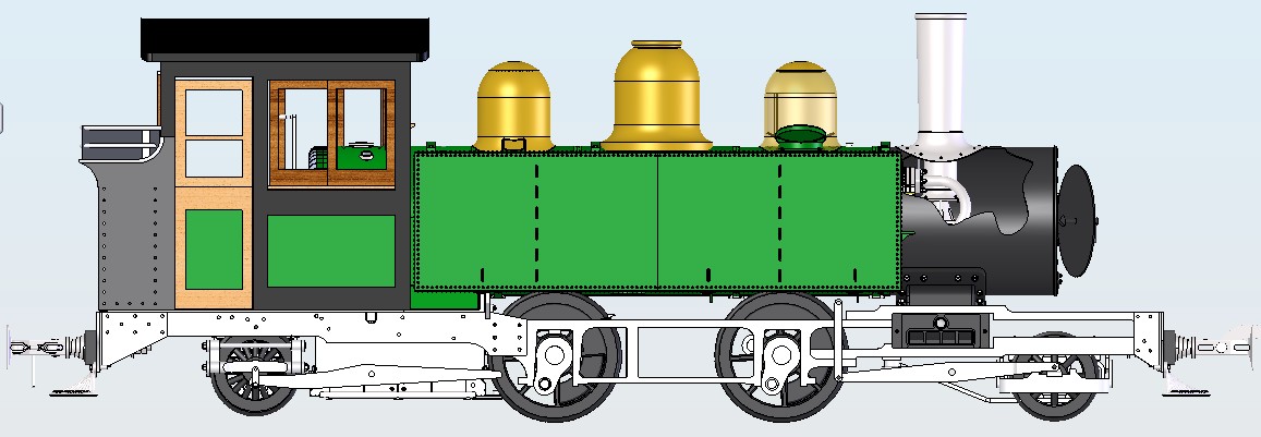
I have started the design and detailing of the coal bunker (another job that wasn't part of my original work program) and you can see what it looks like on the picture below. It is interesting that this assembly has gone through a number of changes over the years. The addition of the top rails to increase the coal carrying capacity are the biggest change and even those have been tweaked to further increase the capacity. Luckly the 1929 version that we are aiming for has the largest coal capacity.
The design for the saddle and cylinders has started. Currently the torch is with Ian Gaylor. He is producing the design layout and doing the calculations to ensure that we get a really good performing loco!
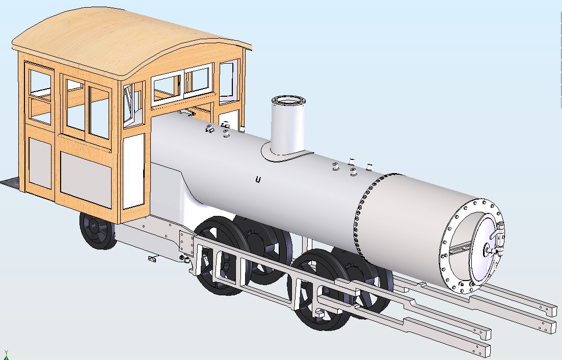
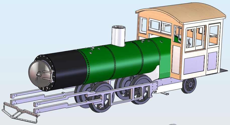
Latest side view. |
Modelling progress up to 2nd December 2011
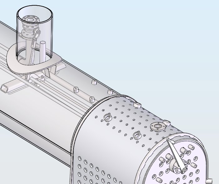
The Saddle is now modelled and awaiting completion of the design for the cylinders before detailing can start. The model of the saddle won't have the welds and some of the rads shown due to the limitiations of the CAD package (software engineers really don't understand welding).
Saddle. |
Saddle section. |
Section through the smokebox. |
Modelling progress up to 5th December 2011
I've gone as far as I can with the modelling of the saddle and it is now ready for detailing. There has been a number of modifications to the draughting now that the blast stand is finished and connected to the saddle and these are mostly complete (subject to a design review with Ian). As I am now held up till the cylinders and valve gear are laid out, I have taken the opportunity to have a first pass at the front pony truck. Still a bit more to do to it but it should be a bit more straight forward than the trailing truck as that has the deeper firebox to cope with. I am reasonably confident that the basic size of the main frame of the truck is as close to the original as possible as I have been able to scan part of the original erection drawing, put it as a back drop to a drawing, drag it to close to actual size by comparing the few dimensions on the drawing to real CAD dimensions and then trace over the shapes. The drawing is quite old and there is some evidence that there has been a lot of "draftsman's license" taken with the scaling. Still, the drawing was only done to enable the kit of parts to be assembled.
Leading Pony Truck. |
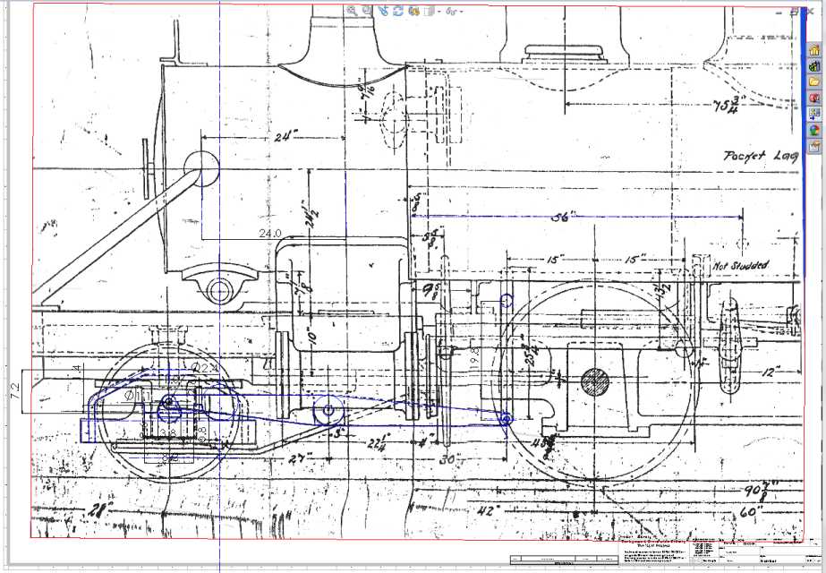
Section of the Original Erection Drawing. |
Side view of LYN with all its wheels on. |
Modelling progress up to 22th December 2011
I have been working hard to get the boiler certification drawing completed. This drawing is an example of the limitations of the modern 3D CAD drawing systems. Because the drawing has to give sufficient information for the insurance companies engineers to sign off the boiler as safe and fit for purpose, but they (apparently) can't/won't cope with the more usual approach of a single drawing for each part and an assembly drawing to show how they are put together so, on the advice of the boilermaker, I have produced a drawing for the completed boiler that I hope achieves the requirement. The thing that make this type of drawing so demanding is that every component has to be fully modelled including all the stays and even the welds as SolidWorks is pants at doing the welds on welded structures. This means that the simplest change can take 10 minutes as the rebuild time of all the components is done.
The image below of the initial version of this drawing will be updated once the drawing is approved. If any one wants a copy for their wall let me know and I will provide a PDF for printing at A0.

Modelling progress up to 27th January 2012
The cylinder assembly design layout is broadly complete so I have been able to get the assembly modelled. Ian and I have had a first pass at a design review of the cylinder design and I am currently updating the model to the latest thinking.
We have a major design review later in February and I am aiming to have the model completed for that.
Section of the left hand cylinder through the cylinder. |

Section of the left hand cylinder through the valve. |
left hand cylinder. |
Modelling progress up to 12th February 2012
The cylinder is complete and looks to be able to deliver the performance needed according to the calculations that Ian has done.
We have a major design review at Alan Keef's works tomorrow and I have the full model completed up to date for that.
The boiler certification drawing has been completed and issued to the certifying authorities. I have also issued a set of detail drawings to the boiler maker so that quotes can be obtained and material ordered - a total of 60+ drawings!.
Also issued for quotation and ordering materials are the set of part drawings for the smokebox. This is also being made by Andy Bennett at Bennett Boilers .
Once the design review is completed and providing that no major issues are identified we should be able to detail the saddle and the cylinders for manufacture. I understand that these components will be the first to be manufactured despite being the last detailed.
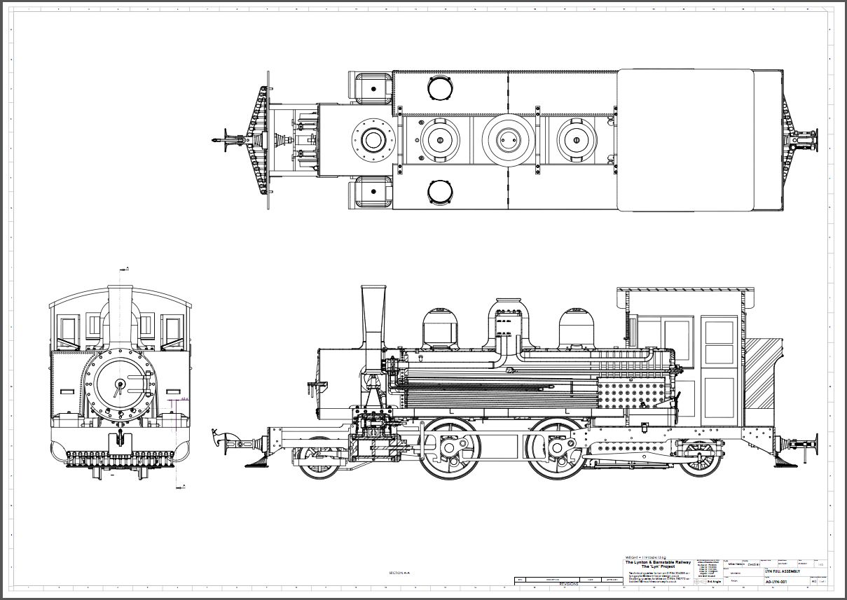
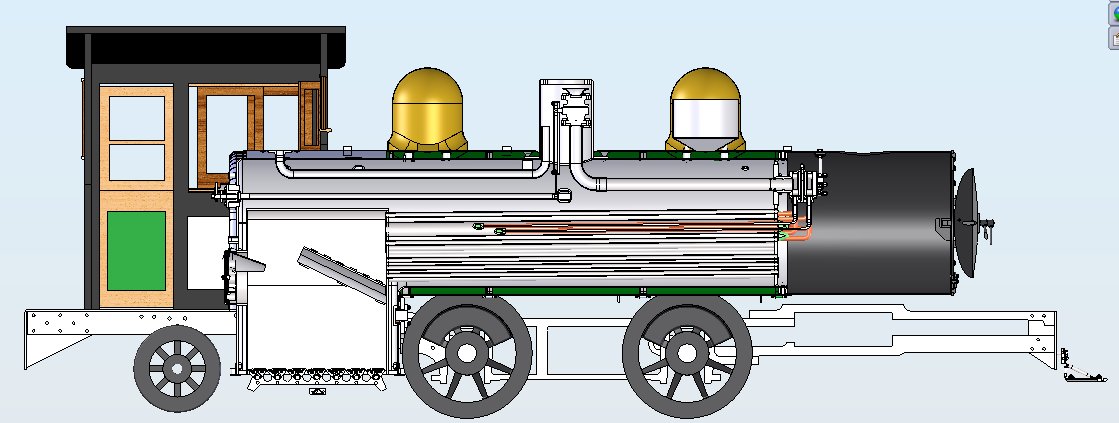
Drawing of LYN at 12th Feb 2012. |
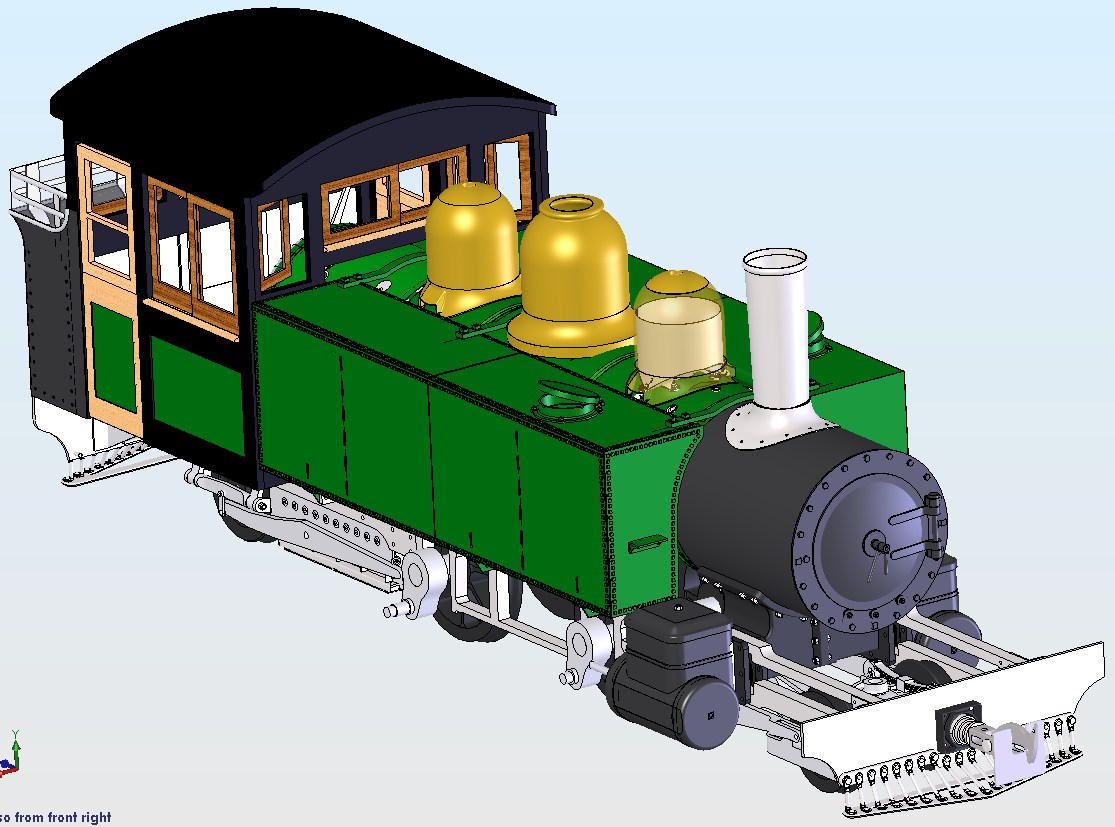
LYN model view 12th Feb 2012. |
Modelling progress up to 29th March 2012
The last month has been mainly consolidation of the work so far. I think that I am about 50% through the detail design work and I have completed around 550 drawings so far.
The Boiler design has been approved by the insurance company's engineer and the construction has started at Bennett Boilers. I am hoping that pictures will be taken during the manufacture and should be available on The 762 Club web site. Ian Gaylor and I have been through a drawing checking program to ensure that we are not at home to Mr Cockup and I hope that we have found all the things that inevitably slip through the detailing process. I will be issuing a final set of boiler manufacturing drawings next week
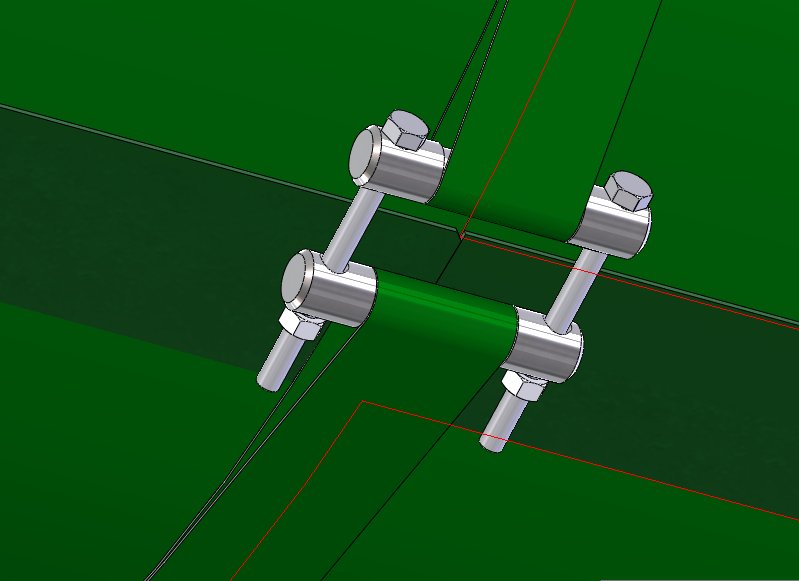
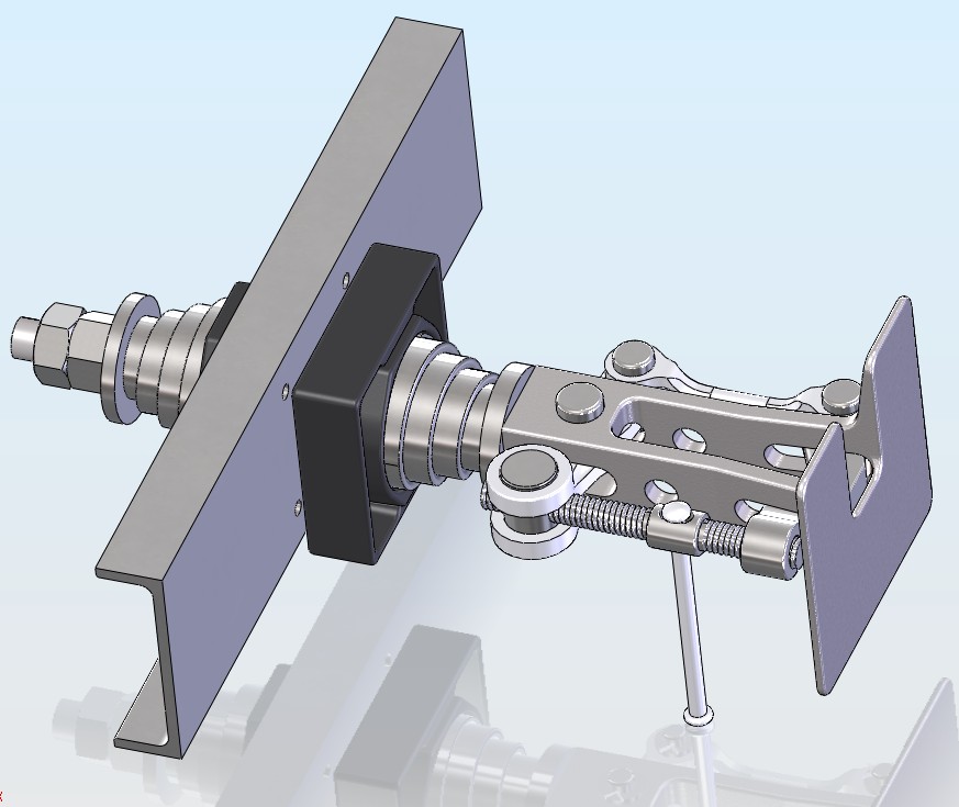
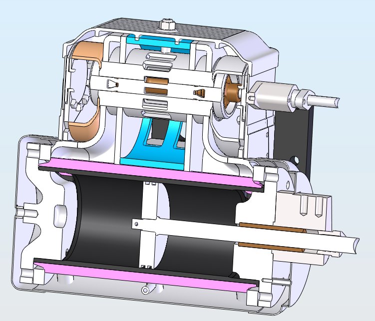
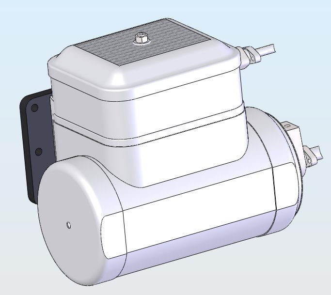
One assembly that needs to be manufactured soon is the regulator valve linkage. This has been waiting for the actual valve to arrive. We had a problem sourcing this valve as, by the time the order was placed, the chosen valve was no longer available. The valve has now been sourced from a different company and is currently in my workshop so that I can model it up to ensure that it all fits together in the boiler. The regulator linkage has become more complex to fit as the original concept of inserting it through the backhead gland housing proved to be impossible once the boiler stays were in place. To get sufficient angular rotation of the regulator valve the driving link has had to be cunningly wrapped around the long boiler stays as shown in the picture below.
The saddle drawings have been issued to Alan Keef for manufacture and the cylinder assembly just needs a final review meeting before the detailing can start. I expect to have the manufacturing package for this by the end of April.
The regulator valve and linkage in the boiler. |
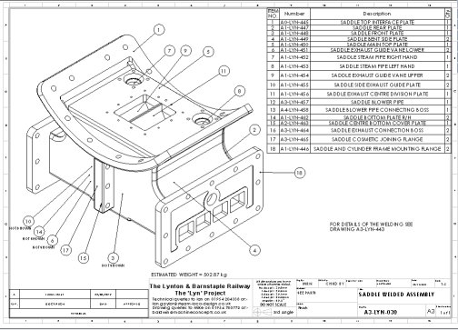
The saddle assembly drawing. |
Modelling progress up to 17th May 2012
The Saddle drawings have now been checked and issued and manufacturing is underway.
The cylinder design is complete and has been reviewed. I have started the detail drawings and should have these ready for checking in a couple of weeks.
The regulator mechanism design has been finished and the parts detailed and issued for manufacture.
The boiler manufacturing is now underway and some of the major components are well started. Here are a few pictures of the work in hand.

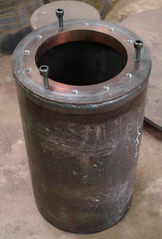
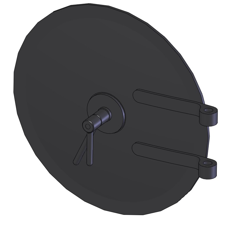
The smokebox tube. |

Another view of the smokebox. |

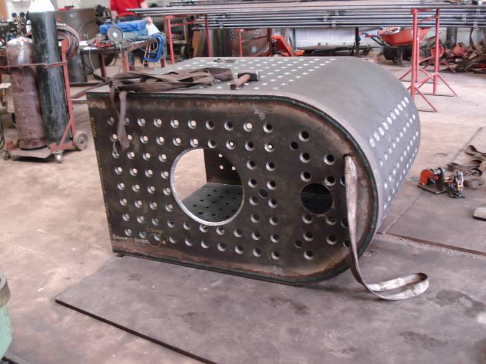
firebox outer wrapper. |

Boiler barrel. |

Firebox inner. |
Five photographs taken on the 10th May 2012, by 762 Club Finance Director Jon Pain, at Bennett Boilers' works
Modelling progress up to 6th July 2012
This Month the work has been to complete the drawing package for the cylinders. This is now mostly complete and the 75 drawings have been issued for checking. I expect that there will be a few more days work before they can be issued for manufacture but we are close. The Saddle is now well started and the profiled plates and formed plates are now with Keefs. The regulator assembly has been started. The boiler continues to advance at Bennett Boilers and here are a couple more pictures:-
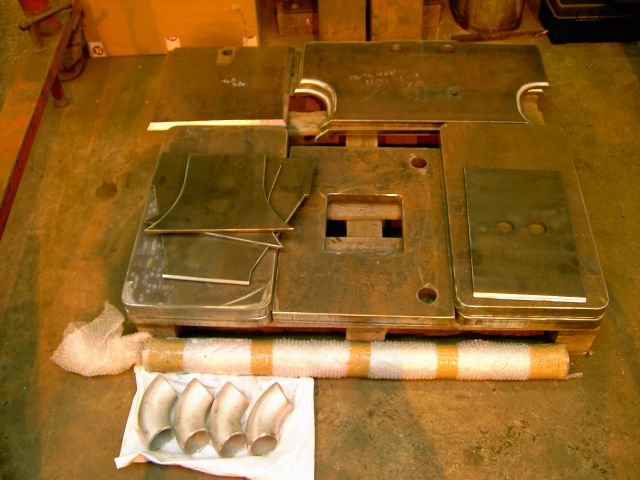
Saddle platework ready for welding. |
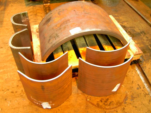
Saddle formed plates. |
Saddle end plates. |
Boiler steam dome. |
Firebox outer wrapper. |
Modelling progress up to 3th August 2012
The detail drawing package for the cylinders in now complete and issued. This has been a real challange to do as realising the original style and shape in a prefabricated unit whilst adding significantly to the performance of the unit is very complex and has taken longer than expected.
The total number of drawings for this assembly is 95 including a couple of quite complex drawings. The most demanding drawing is the one showing the stages of the welding of the cylinder unit. If you want to see this drawing I have put a PDF of it here
The next area to be detailed is the motion. Ian is well advanced with the design and I expect that I will be able to start modelling it in about a weeks time. I plan to produce a model that can be moved so that we can measure and check all the timings and clearances.
Modelling progress up to 11th August 2012
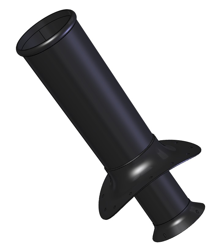
The drawings for the smokebox door, the cowcatcher, the blast stand and the chimney have now been issued for checking.
 |
 |
 |
 |
| Smokebox Door |
Cowcatcher |
Blast Stand |
Chimney |
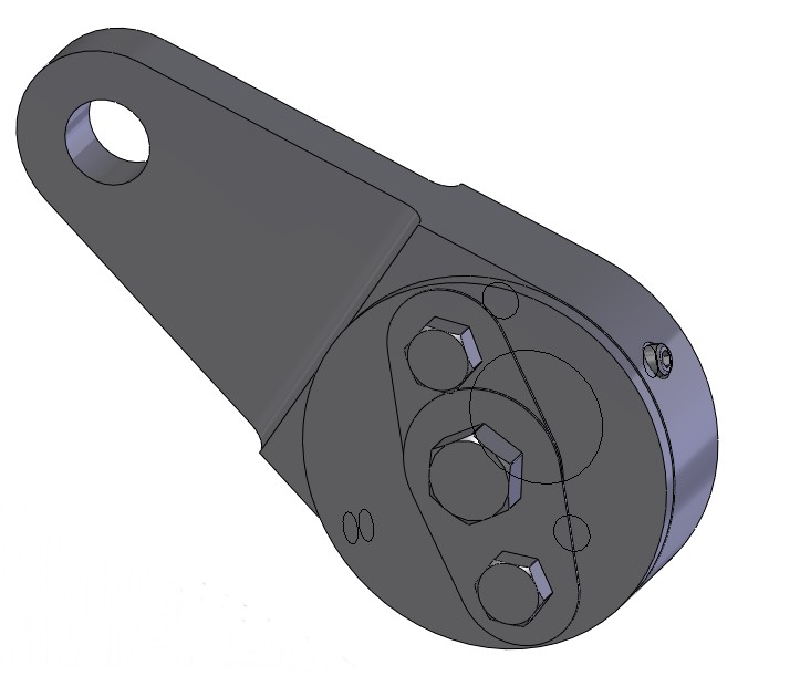
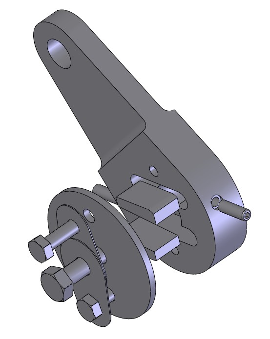
Another item that has been finished is the regulator valve lever. This is the lever that mounts on the shaft of the actual valve. This shaft has only a couple of flats to do the driving and, because the working environment is very challanging and the loads are significant, this lever often becomes loose and is a significant detriment to the driving experience. To overcome this problem Ian Gaylor has come up with a clever design that not only ensures that the lever has no lost motion but is also easy to assemble and any future wear can be taken out. The design relies on 2 wedges that slide along 2 slots each driven by a grub screw. The wedges are held in with the large washer and the whole assembly is prevented from coming loose by the 2 locking tab washers that will be bent up to lock the flats on the bolts.
 |
 |
| The assembled lever |
Exploded view of the parts |

The parts for the regulator ready for assembly. |
Modelling progress up to 8th September 2012
Ian has finished the design layout of the motion and I have started modelling it up ready to detail it. I am doing the model and the assembly so that the mechanism can be cycled. I can't show that here yet but when I get time I will aim to do a small movie to show the parts moving.
I am hoping that I will be able to cycle the full mechanism including the valve gear once I have it modelled. This will be a bit down the road as Ian is still working on the design.
I shall probably not be moving as fast as I am now well ahead of the build and need a rest!!
Click on the picture to see the wheels turn |
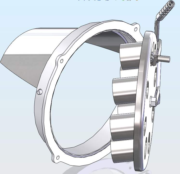
Boiler making progress up to 18th September 2012
The manufacture of the boiler is progressing well at Bennett Boilers and Andy Bennett has sent me a few pictures of the work in progress.
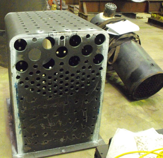
The firebox inner assembly. |
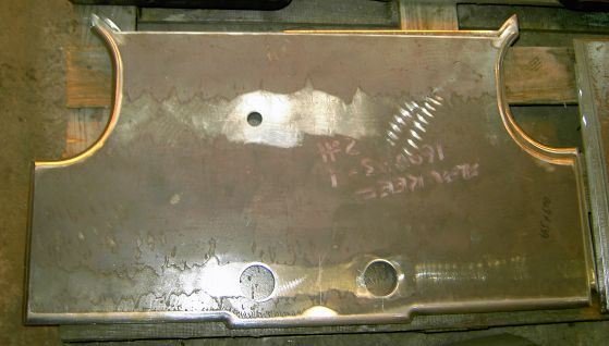
The front tube plate. |

The barrel and firebox wrapper assembly. |

The firebox wrapper and barrel from the firebox end. |
Four photographs taken on the 18th September 2012, by Andy Bennett at Bennett Boiler works
Modelling progress up to 20th November 2012
Ian has now passed the design layout for the valve conrod and the rocking shaft assembly to me. I have modeled the assembly and added it to the motion model. I have also detailed the parts so that we are ready to make them when the funds are available. I am expecting the rest of the valve mechanism soon. The centre part of the chassis frame is now close to finished with only the wheel bearing area to be designed.

The the valve conrod and rocking shaft assembly. |
Modelling progress up to 5th December 2012
Ian has now passed the design layout for the expansion link mechanism to me and I have modelled it ready for detailing. I expect that Ian and I will need to get together to go through the design to be sure that it does what it should..

The the valve mechanism expansion link and weighshaft assembly. |
The the valve mechanism assembly on the chassis. |
Click here for an animation of the valve mechanism in motion
Modelling progress up to 15th December 2012
I have finished most of the modelling of the valve gear and the motion. The valve gear is now detailed and awaiting checking. The motion is still to be detailed. Here is a picture of the model so far with the motion and the rocking lever assy added. Click on the model to download a sectioned A0 PDF of lyn.
Lyn modeled assembly. |
Boiler making progress up to 15th December 2012
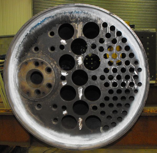
The manufacture of the boiler continues to progress well at Bennett Boilers. Jon Paine has sent me a few pictures of the work in progress. click on the pictures for larger images.
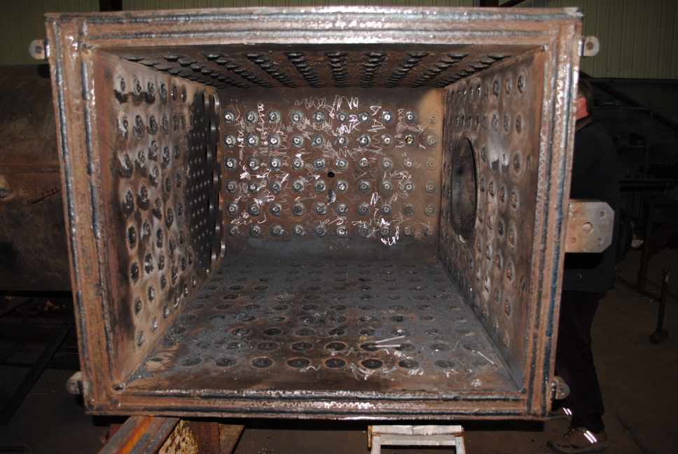
The firebox looking from the bottom. |

The front tube plate. |
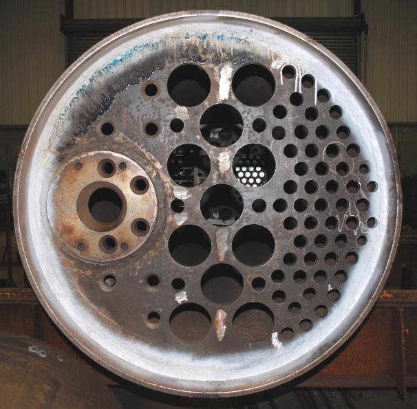
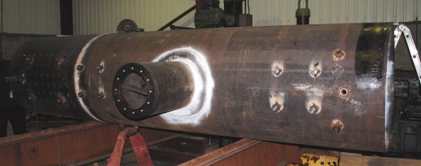
The boiler looking from the front assembly. |
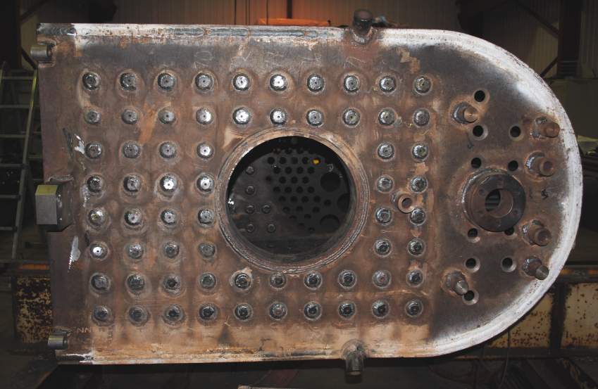
The backhead. |
The boiler looking from the top. |

The firebox wrapper from the top. |
Four photographs taken on the 15th December 2012, by Jon Paine at Bennett Boiler works
I talked to Andy Bennett today (20th December 2012) and he is currently fettling the stays after welding them in. He expects to have the boiler ready for stress relieving early in January 2013 and it looks as though the main part of the boiler will be finished early February 2013. This leaves only the superheater and the smokebox to do.
This blog continues on page 2
Go back to Mike Nelsons Home Page
This site is created and maintained by Mike Nelson for his own pleasure
© 2010/11/12/13 Mike Nelson


