ST G51
Improving the stunt performance of the Supertigre G51

Page 1
My Mo-Best

Introduction
In 2006 I graduated from flying class 2 Stunt where I had been using a Brodak 40 powered
Profile Oriental. This model was replaced by a Profile Mo-Best designed by Larry Cunningham and powered by an un-modified SuperTigre G51. The original set up with a standard G51
By the middle of 2006 it was clear that the motor was not performing as well as I wanted. It would speed up considerably at the first sign of any wind and it was hard to get a reliable setting for speed. I had 2 of these engines and they both performed the same way. I talked to John Dixon, an experienced engine tuner, who had made a number of these engines perform well in the hands of John Benzing.
John Dixon advised the following modifications:-
  1. Reduce the exhaust/transfer overlap from the standard 1.3mm to 0.6mm
  2. The boost port is not changed
  3. Modify the combustion chamber shape
  4. Increase the venturi diameter (only if more power needed)
  5. Fit light tube silencer with an internal volume of approx 3.5 times the swept volume of the engine and an Ø8mm outlet. John suggested that the outlet might need to be smaller(see below).
    Silencer drawings
  6. Use Master 12x6 propeller
  7. Use Enya #3 plug
  8. Use all castor fuel

I flew the engine with these modifications for the rest of the year and, although it was much improved, it still was a handful when the wind was anything other than a light breeze. I modified a second engine to the same condition and they both performed in a very similar manner. I spent some time trying head shims and different venturi sizes to get the best I could from the engines.
At the end of 2006 I obtained a third G51 and decided to use it to experiment with some other ideas.
I made the following modifications:-
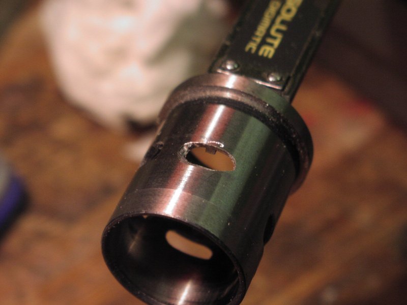
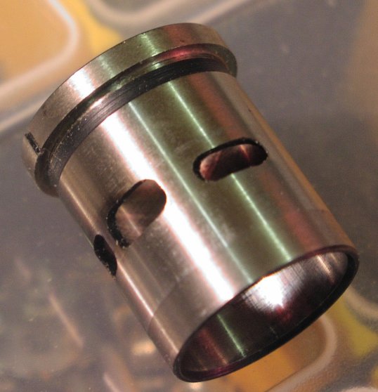
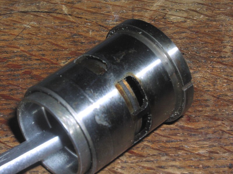
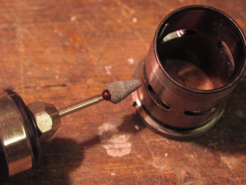
  1. Block up the boost port (the one opposite the exhaust port)
  2. Modify the combustion chamber shape as for the John Dixon Method
  3. Sleeve the crankshaft bore from Ø10mm to Ø8mm
  4. Increase the venturi diameter to Ø7.5 (this size after some testing of other sizes)
  5. Fit light tube silencer as described above but with the outlet sleeved to Ø6.5 (see drawings)
  6. Use Master 12x6 propeller
  7. Use Enya #3 plug
  8. Use 20% all castor fuel with 5% Nitro
This Engine was a significant step forward and, once I had found the best head shimming, silencer outlet diameter and venturi size, the engine performed well even in the wind.
During the second half of 2008 the performance deteriorated and the engine became very unpredictable, unresponsive to needle changes and prone to running away in the slightest wind. After much head scratching the problem was traced to the crankshaft bearings which were too loose on the shaft and were probably skidding. Loctiting them only made the problem worse. The solution was to fit bearings of a looser grade - C3 - also loctited to the shaft. During the search for the lost performance I had tried silencer pressure and that had made a noticable improvement. Combining this with the careful refitting of the crankshaft bearings has returned the engine to its previous good performance and it seems easier to find a good setting as the needle responds in a very predictable way now - much better than it was even when the engine was performing well. I am also now using 7% nitro and have adjusted the shimming to further improve things.

Index

Modifications to Engine No. 1 & 2.
crankcase 1 crankcase 2
unmodified cylinder. cylinder after the port has been reshaped to the recommendations of John Dixon. The top edge of the 2 transfer ports have been raised until they are 0.6mm below the top of the exhaust port
crankcase 1 crankcase 2
An easy way to measure the difference in height between the top edge of the exhaust port and the top edge of the transfer port is to insert the piston into the cylinder and slide it up till the top edge is just at the top of the transfer port. You can then use the shank of a twist drill to measure the gap between the top of the piston and the top of the exhaust port.
My method is to measure the distance down from the top of the cylinder to the top of the exhaust port using a a set of digital calipers then, add 0.6mm to the measured value and grind the transfer port top edge till it just reaches the caliper tail.
Whilst I was preparing this description I measured some parts to check the dimensions and found an interesting thing. The port timing of the Chinese manufactured engines is quite different to the Italian made engines. The actual measurements are as follows:-
  • Chinese transfer port top = 16.4 from top of cylinder
  • Chinese exhaust top = 15.2 from top of cylinder
This gives an overlap of 1.2mm (I was expecting 1.3mm)
  • Italian transfer top = 15.8 from top of cylinder
  • Italian exhaust top = 14.2 from top of cylinder
This gives an overlap of 1.6mm - significantly more than the Chinese build version.
I have no idea what the implications of these differences are!

crankcase 1 crankcase 2
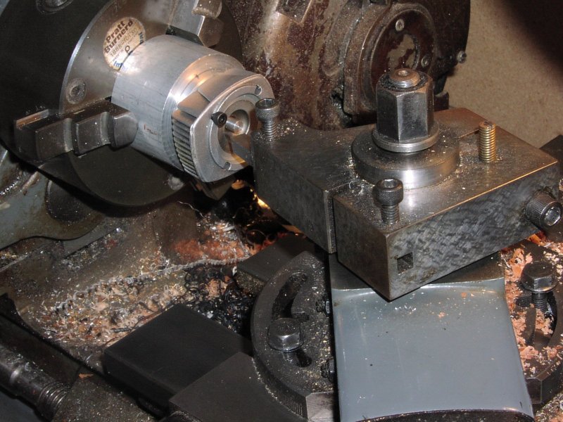
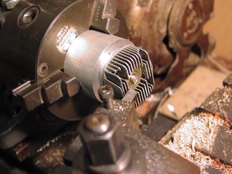
The head is mounted on the fixture and the top fins skimmed to provide an accurate mounting face for the next machining operation. The head is reversed on the fixture ready to machine the chamfer to the squish band.
head machining drawing
crankcase 1 crankcase 2
the cylinder head before machining. cylinder head after machining.
Modifications to Engine No. 3.
crankcase 1 
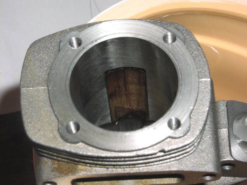
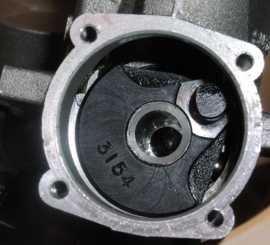
The boost port is blocked with a hand fitted balsa strip. This one has survived a full seasons flying. It isn't glued in just a firm fit in the crankcase.

Crankshaft Modifications
crankshaft1 crankshaft2
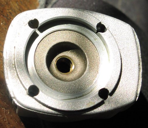
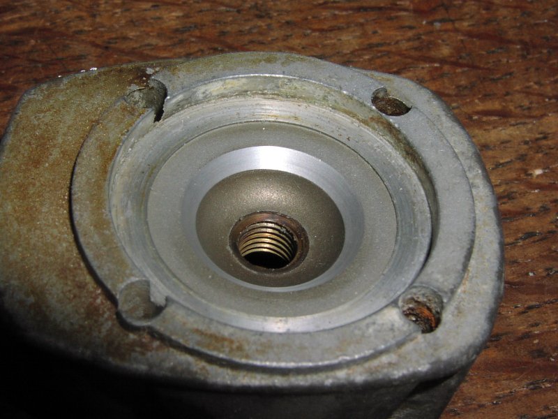
The crankshaft inlet port before it is opened up. The shaft bore is cleaned out with a piece of wet&dry on a dowel to make sure it is free from contamination etc. A piece of aluminium rod is machined to Ø10mm to a firm sliding fit in the bore. This is fitted into the bore using Loctite High strength retainer. The bore is then drilled to a diameter of 8mm

Crankcase Machining
crankcase 1 crankcase 2 crankcase 2
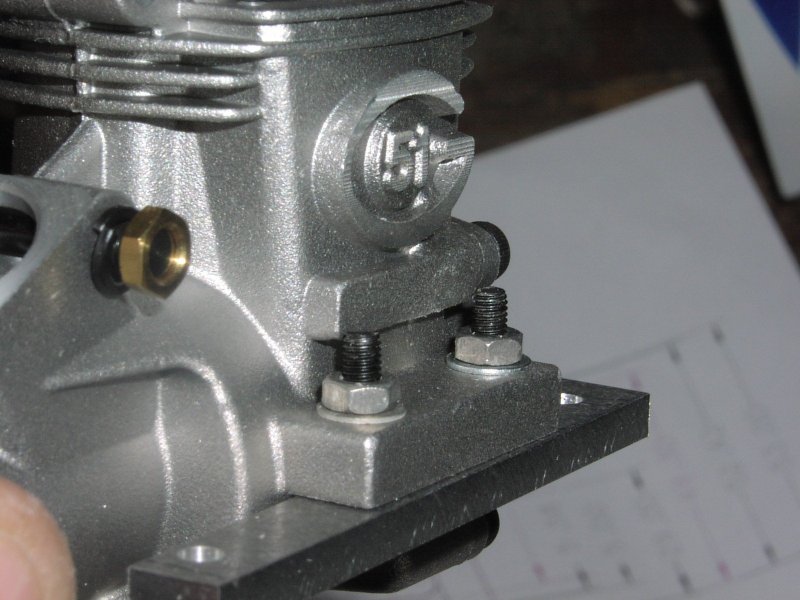
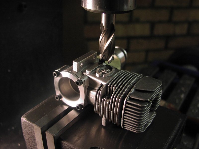
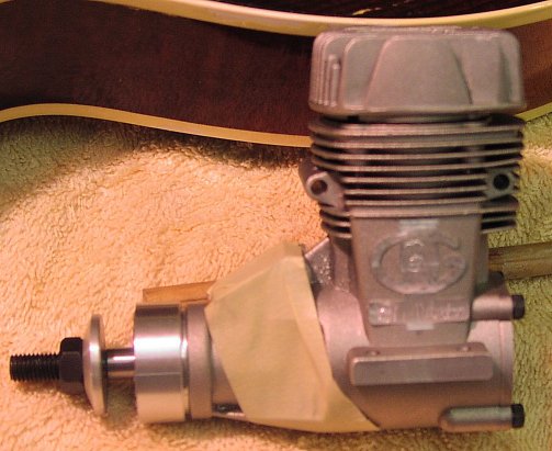
The Chinese version of the SuperTigre G51 is left with some excess lumps on the side of the casting. These get in the way of the mounting screws and don't perform any useful function. The original Italian version of the engine had the same lumps but they were much shallower and didn't interfere with the mounting screws.
All openings in the engine are plugged with tissue and the engine is held in the milling machine vice by a lug so that the offending lumps can be machined off.
Page 2. silencer & venturi Drawings
Page 3. Further Developments
© 2008 Mike Nelson. All rights reserved.

This description has been put together by Mike Nelson.
Go back to Mike Nelsons controline Home Page Go back to Mike Nelsons Home Page

This site is created and maintained by Mike Nelson for his own pleasure