front exploded view
Brian Turner's custom stunt engine

Page 7
rear exploded view

The drawings.
Back To the Index

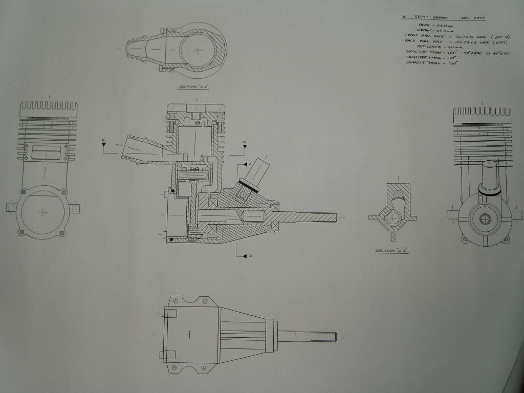
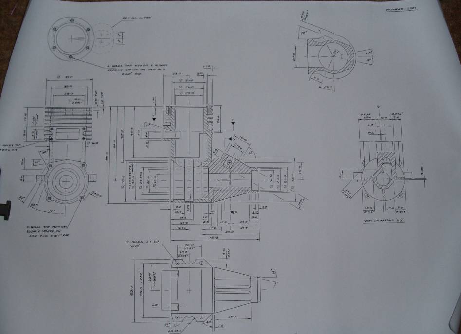
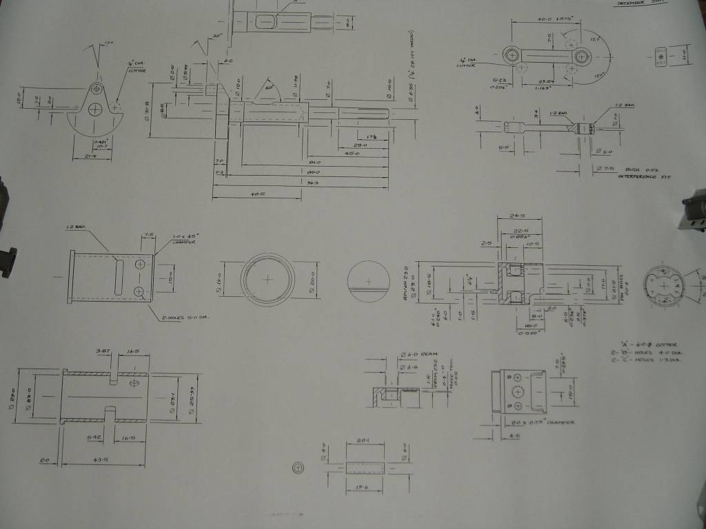
I have worked from Brians original drawings to create an accurate 3D model using SolidWorks. From this model I am producing component drawings in PDF format. Currently I have completed the drawings produced and they are available below. Most of the main drawings are checked and should be complete. If anyone is planning to start making an engine from these drawings I would strongly suggest that you email me so that I can keep you posted with any changes, updates or improvements.
You will see that there is one major difference between the original prototype and the drawings available here and that is the venturie is now on the engine centreline not offset as it is in Brians prototype. The experience of using the original engine in competition for the second half of 2008 has indicated that the slightly improved engine balance is not discernable in the running and is an unnecessary complication in the machining.
I have also included a normal prop driver for any one who prefers to use a commercial spinner

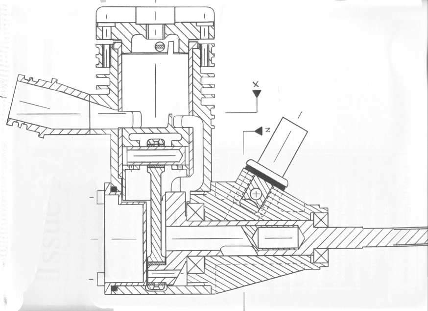
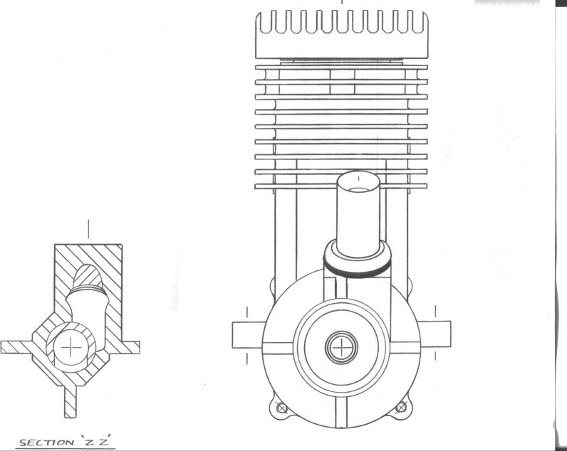
There is also an easy to use 3D model of the assembled engine that can be spun, sectioned and exploded to further explain the design. For more information on how to access the reading program to use this model please go to the CAD TOOLS PAGE

Click on a drawing link to open or save.

Errors and updates

The following drawings have been updated:-

  • Crankcase assembly/machining - overall height added 25/02/09
  • Cylinder head - thread now 1/4-32 UNEF corner rad now 1.5 was 0.5 duplicate dimension deleted 25/02/09
  • Cylinder - diameter symbol added to bore diameter dimensions 25/02/09
  • Plug Baffle - - added to list 25/02/09
  • Piston - added to list 25/02/09
  • Engine Assembly - updated to call up plug baffle 25/02/09
  • Prop Driver - grooves added 26/02/09
  • page 6 - liner taper should read "honed with a taper of 0.089mm (0.0035")top to bottom".(29/03/2011)
  • page 6 - piston turned diameter should read "The piston is turned to 0.012mm (0.0005") oversize.(29/03/2011)
  • Reduced size assembly drawing split into 2 sheets and added in black and white. 06/01/2014
  • All the pdf files recreated to solve some rendering of the test problems. 06/01/2014

Brians Original Drawings
drawing sheet 1 crankcase 2
crankcase 1 crankcase 2
previous Page - Next Page
© 2008 Mike Nelson. All rights reserved.

This description has been put together by Mike Nelson using pictures taken by Brian
Go back to Mike Nelsons controline Home Page Go back to Mike Nelsons Home Page

This site is created and maintained by Mike Nelson for his own pleasure