
(updated 08/02/16)
|
(updated 08/02/16) |
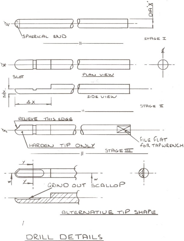 |
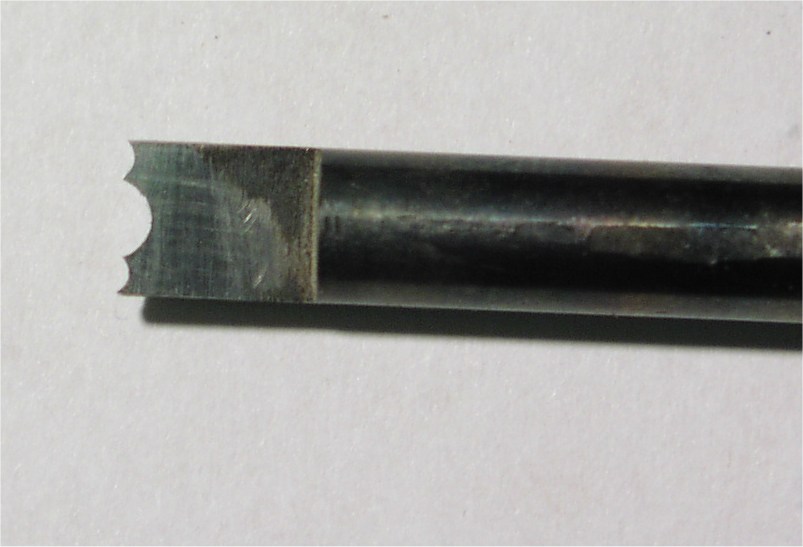
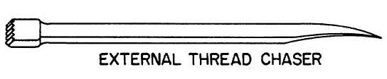
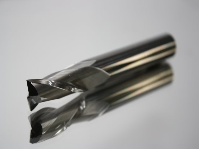
The bore of the chanter is the most important part of the instrument and must be as accurate and as smooth as possible. There are a number of different styles of drill that can be used to produce the bore including the ordinary twist drill but, although I know of makers who use the twist drill, I have found it very prone to wandering and the bore produced is generally less accurate and somewhat rough, so I will concentrate on the style of drill that I use. This is a 'D' bit drill, and if carefully made, in accordance with these instructions, will produce smooth, straight holes. This type of drill was first used in the early manufacture of muskets and other artifacts requiring a long straight holes in the days before modern accurate machines were available. Start by selecting a straight rod of "silver steel". This is a medium carbon steel supplied as a ground rod in lengths of 330mm (13") in a wide range of sizes. For the chanter, which will be reamed after drilling, a diameter of 4mm will be correct. Cut off the first 2mm of the rod as it is likely that this has been hardened by the method used to cut the rods to length. Put into the lathe with about 20mm out of the chuck. Start up the lathe and, using a fairly fine file, shape the end to a hemisphere. Smooth the end with emery paper to remove the file marks but take care not to affect the the outside diameter of the rod as it is important that the rod diameter is left untouched. Remove from the lathe and grip in a vice with the same 20mm sticking out and file a flat down to the center of the rod for the full 20mm . Take special care with this operation, the flat should be parallel to the centreline of the rod and just (not more than 0.05mm (.002") short of the centreline. You should now have a "D" shaped section 20mm long finishing in a half hemisphere. File a groove across the flat, 3mm wide and 0.5mm deep. This is to grip the plug of swarf to ensure its easy removal. Relieve the trailing edge of the hemisphere to avoid rubbing during cutting the hole. Harden the end of the tool as described in the paragraph on hardening The flat must now be rubbed on a smooth oilstone to sharpen the cutting edges. File a flat on the other end to grip in a tap wrench and the drill is ready for use. |


 |  |
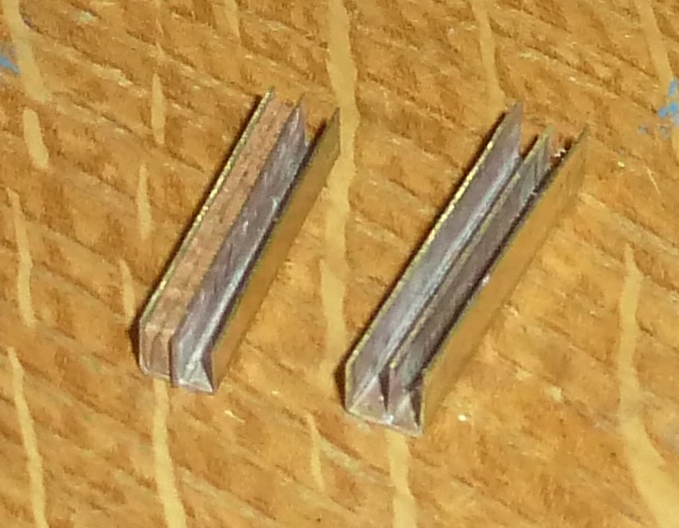
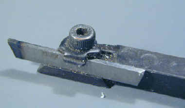
| The form tools are made from 6mm diameter silver steel. A piece is cut 40mm long and a flat filed about halfway down one end but, unlike the "D" bit drill, the flat is angled back from the front edge. The front of the tool is filed to the shape required using needle files until the desired shape is obtained taking care to create some relief so that only the cutting edge of the tool touches the work. Try the tool out on a scrap piece of wood and adjust the shape until it cuts well and gives the right shape. The tool is hardened in the same way as the "D" bit drill and the top face polished to help the tool give a good finish to the work. Form tools can be made to do all of the decorative work on the chanter and, although it can be argued that the artistic design process will be constrained by them, I have found that they are capable of a fineness of shape and repeatability difficult to achieve by hand turning methods. A limitation however can be a tendency to pull chips out of the wood when used on less even grained woods like rosewood or tulip wood or when the tool is used to cut a shape which is either too fine or too deep. |
 - a vital tool for any lathe user.


Water manometer for pressure measurement |
The Manometer is made from a wooden back plate, 2 glass tubes of about 6mm diameter
and a couple of lengths of rubber tubing. I used the red rubber tubing used to
connect a Bunsen burner in school labs of the 60's but any similar tube will do. The main requirement is to be able to connect the top of the small g drone standing part easily onto the tube. I mounted the glass tubes to the backplate using "P"clips These are intended for clamping wires in electrical/electronic installations and should be available from places like Maplins or Radio Shack or other shops that cater for the electronics hobbiest. Please note that the measurement of pressure is the difference in the height of the water in the 2 tubes so that if the water raises up 1 inch in one tube it will fall 1 inch in the other tube thus indication a pressure of 2 inches water gauge. click on the image on the left for an bigger picture and print it at A4 |
© 1997 Mike Nelson