Page 4
|
Page 4 |
|
 |
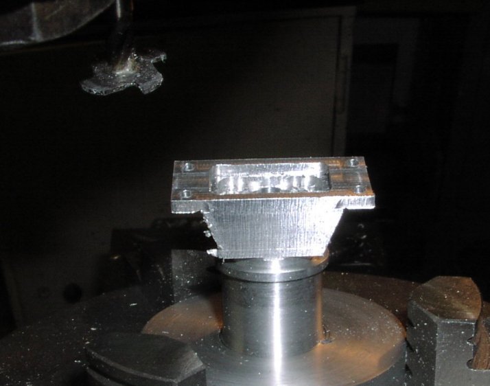 |
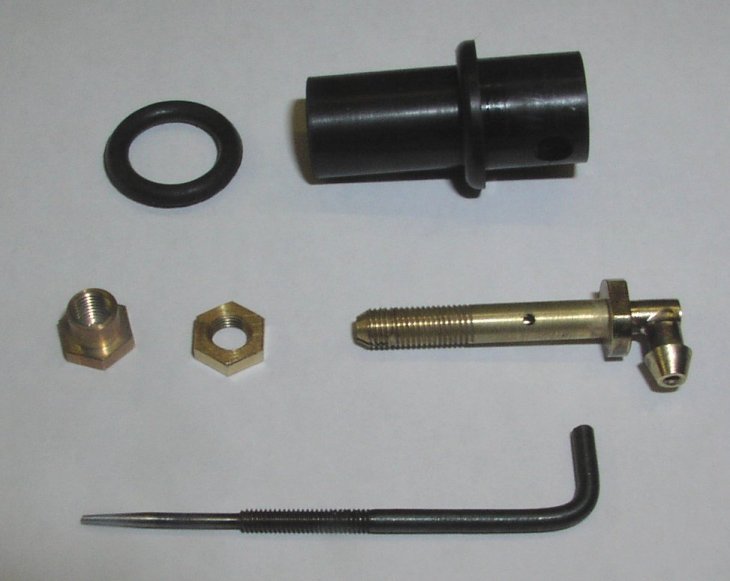
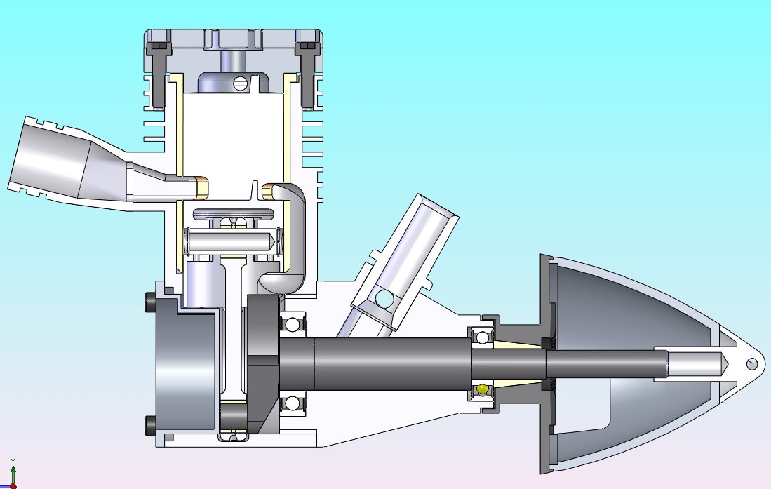
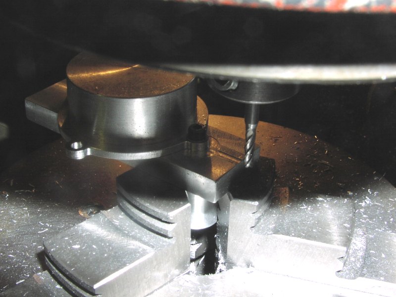
| Needle valve assy. The fuel pipe has to be at right angles as the offset of the venturi puts it too close to the side of the cowl to bend the fuel tube without kinking. | The silencer manifold is a tricky bit as it is a mass of different angles. Shown here in the dividing head offset from the vertical to machine the flange. The cutter is a woodruff cutter and is used to machine the area under the flange. |
 |
|
| Back in the lathe to machine the oring grooves and part off. From here on the manifold is finished to the final shape by hand. | Finished to final shape - 75mins hand work from the finished machined piece. |
 |
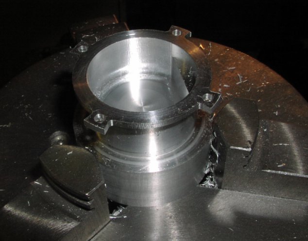 |
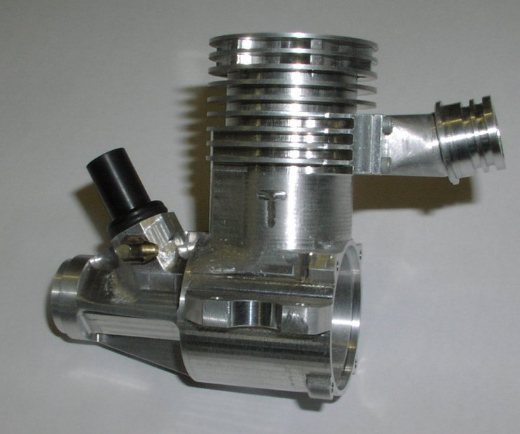
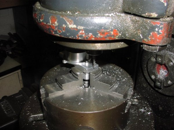
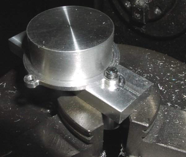
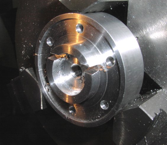
| This is the trial assembly of the needle valve assy and the silencer manifold. | Machining the back plate. The turning has already been done in the lathe. the bore has been machined to the maximum round diameter and now this inside round is opened up to the "D" shape in the dividing head. Also in this setup the flange is machined and the holes drilled. The extra material used to hold the backplate in the chuck will become the new cylinder head once the finished backplate is parted off. |
 |
 |
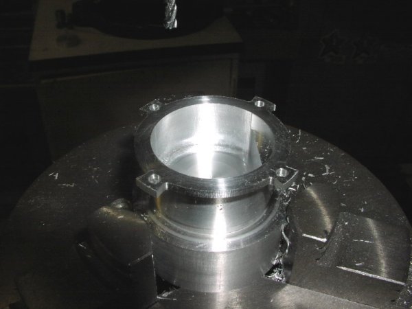
| The back plate set up in the dividing head to machine the backplate mounting lugs to the final round shape. Another of Brian's simple fixtures make this a straightforward operation in the dividing head. | Close up of machining the backplate lugs. |
 |
 |
| Using the dividing head for this machining doesn't leave very much room under the head of the miller but Brian prefers the dividing head to the rotary table for this operation and the dividing head is a full size one. |
 |
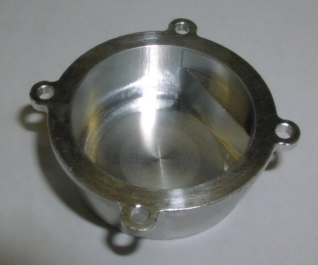 |
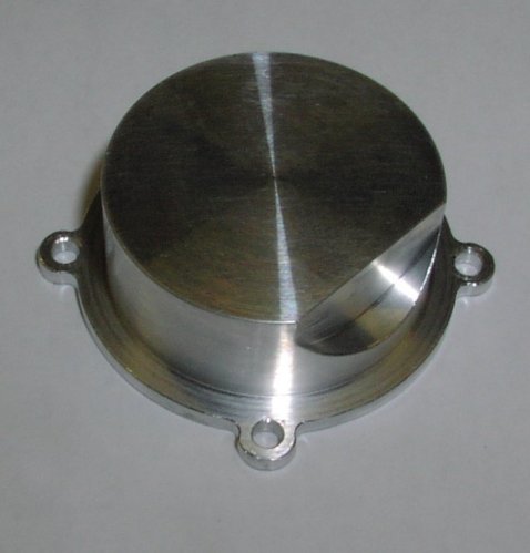
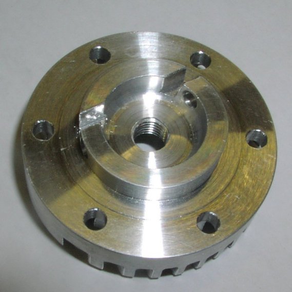
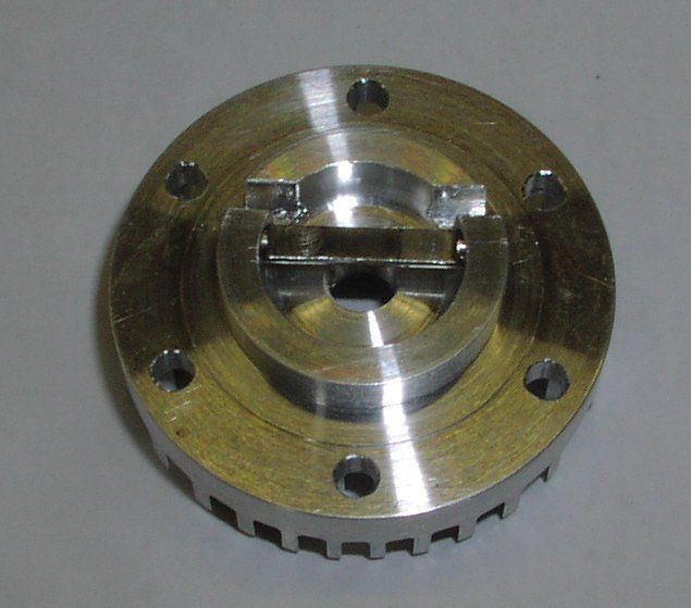
| Finished backplate showing the cutout for the piston. Brian has made a considerable effort to reduce the crankcase volume to improve the pumping of the engine. During the development of the Stalker he has been using he did some back-to-back testing that showed a real benefit from this. | Outside of the backplate. You can see the transition of the turned to the milled parts of the inside shaping. |
 |
 |
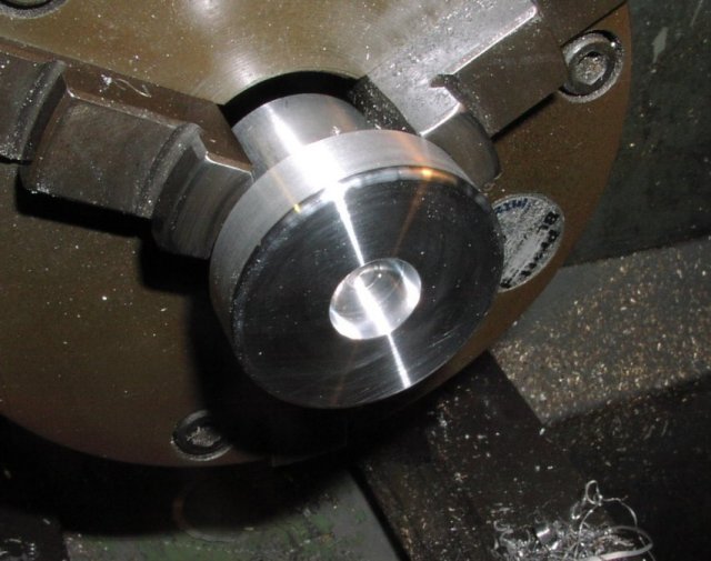
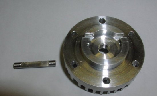
| These are the parts need to machine the head. On the left is the head blank now finish machined where it fits into the cylinder but the combustion chamber is not machined at this stage so as to give plenty of thread depth for the bolt. The middle component is a machining fixture with a bore the same as the cylinder and the bolt on the right is 1/4"X 32tpi to clamp the head to the fixture using the plug thread. | Here is the blank and the machining fixture assembled ready for the lathe. |
 |
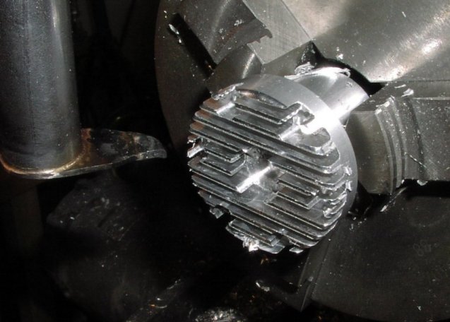 |
| Faced to the final thickness, plug recess bored and the radius around the edge of the fins machined. | Mounted in the dividing head using the same fixture for machining the fins. The cutter Brian is using is one he has made himself. A small piece of high speed steel is silver soldered to the end and ground. This sort of cutter takes a lot of care to use as the cutting forces are quite high. |
 |
 |
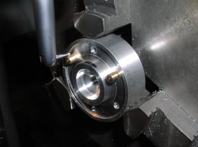
| Setting up the head to machine the clearance for the baffle and the hole for the plug shield. The head is held in the chuck of the dividing head in a split ring. The setting pins are in the head mtg holes and the direction of the fins is marked with a felt tip pen. Because Brian takes a lot of care in the size and position of the head mounting holes he can rely on them for setting later in the machining. | Baffle recess is machined with a Ř75mm x 1mm slitting saw. The slot is first machined with the dividing head parallel and then the angle is machined with the head angled. |
 |
 |
| The plug shield hole machined - in from both sides as it is too long to do from one side and expect it to be straight. Also it is 1/16" offset from the centre so the machining is onto a slightly angled face. | Plug baffle pin machined ready to part off. made in stainless steel it has been turned in the lathe and the centre portion that crosses the combustion chamber thinned down by machining the flats shown here. |
 |
 |
| Head and pin finished. | and assembled. The pin is loctited in to make sure it doesn't rotate. It can't fall out (unlike the Retro version that is pressed into a hole) as it is fully located in its hole by the cylinder walls. |
 |
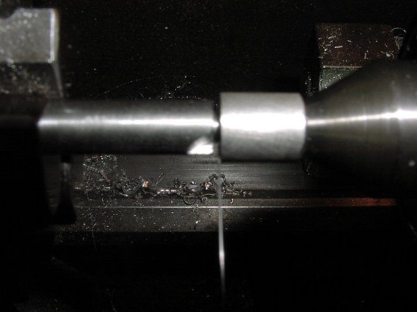 |
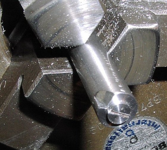
| Jig to make the gudgeon pin circlips. Sorry the picture is not sharp I may try to get a better picture later - the jig is quite small!. It is a short turned diameter - trial and error to get the right diameter so that the clip is the right diameter when it is in the relaxed condition. The wire Brian uses is Ř0.4mm. The slot in the end is 0.3mm deep so that the wire can be clamped into it by the pad on the tailstock. The edge the wire bend round as it leaves the slot is radiused to ensure that there is not a stressed part of the clip that might break off as it would do a lot of damage if it did. | The tailstock with a pad fitted on a rotating centre holds the Ř0.4mm wire into the 0.3mm deep groove while the chuck is rotated by hand nearly 2 revs to allow for the unwind. the second turn is on the chuck side of the first wind not over the top of the first wind as that causes a small kink in the clip. |
 |
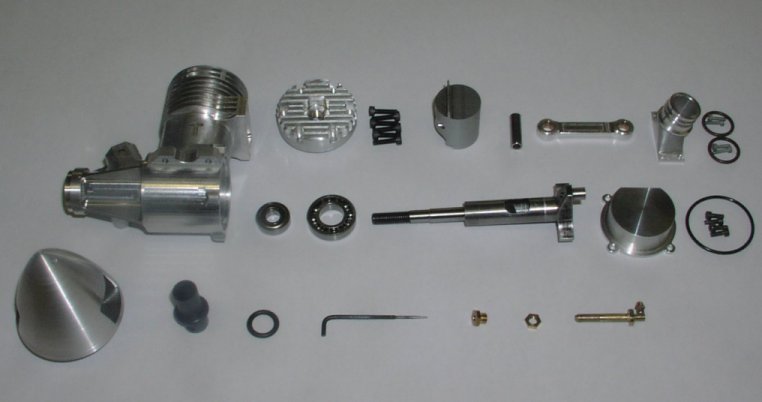 |
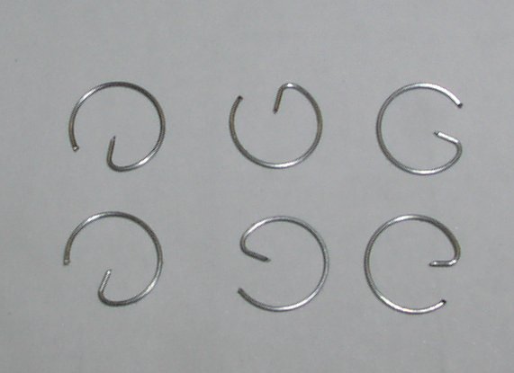
| Finished circlips. | All the components ready to assemble You will see that the cylinder is not back from the Ukraine where is has been sent for the chrome plating. |
|
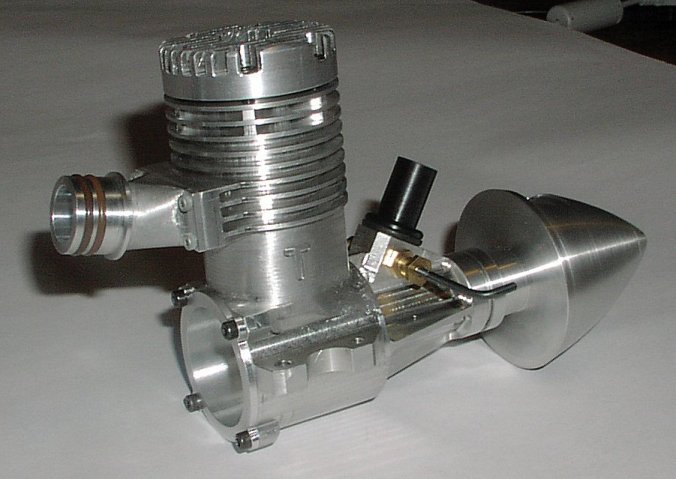 |
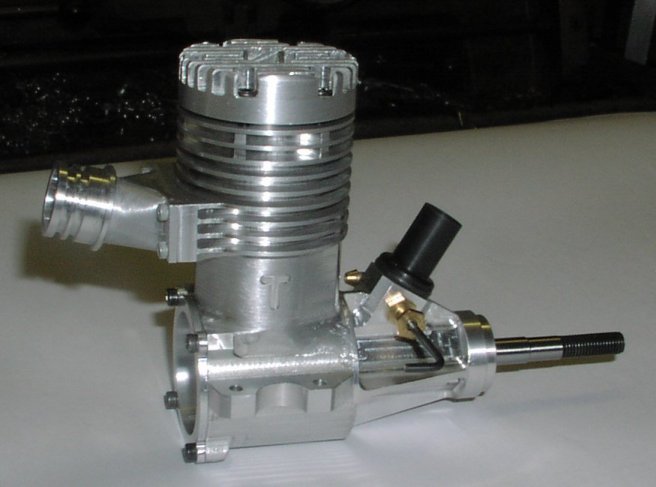
| Assembled engine. | Fitted with the spinner. The spinner backplate is also the prop driver. |