Building wings on glass
A description by Robert Johnson
I don’t think there is anything new here, I’m sure others have thought of this approach or something like it when building. You may notice some similarity to the Lincoln log or Millennium wing jig method. This is my take on it and I urge you to experiment and modify it, if need be to make it work for you. Here goes.
Use straight wood for everything but especially for the leading and trailing edges, this saves many headaches down the road.
The wing jig is made from a glass plate and 1.5 in. aluminum “L” channel.
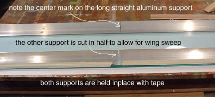
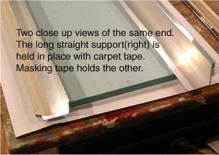
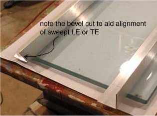
I use a 1/2” thick 12 x 48in. glass shelf (‘cause that’s what I had on hand) but I believe that 1/4” glass of similar or greater dimension should work fine. The “L” channel supports are made of 2-11/2x 48” lengths. One is left straight while the other is cut in half. The cut sections have alternate beveled ends so they can be placed together to support a swept LE or TE. Longer supports can be used if desired. The long straight support is attached to the glass with double stick carpet tape. The others are held down with masking or vinyl tape. Cloths pins that have been reversed are used to hold the LE & TE in place against the supports. 18 to 24 of these is a good number to use.
Cut your wing ribs as accurately as possible. The rib set I used for the photos is for an upcoming Shark 15. Please note that the wing I assembled in the photos is not going to be used, it was created for demonstration purposes only and no glue was applied. This demo was set up and photographed in about an hour. I would take greater care and more time to accurately set up a wing I would use. The process; however, would still be much the same. The next wing I do set up for use, I will photograph and document the steps.
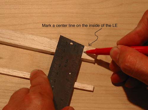
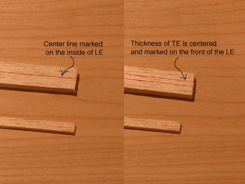
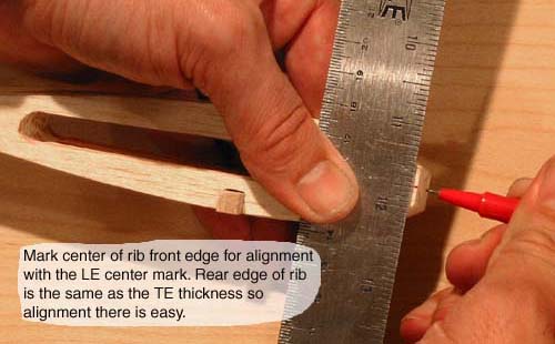
The LE stock is 5/8 x1/4 balsa and the TE stock is 1/8 x 1/4 balsa. Using a red Flair pen I marked a centerline on the inside length of the LE. Next I centered and marked the thickness (1/8”) of the TE on the front length of the LE. The front side marks allow easy alignment on the aluminum supports. The TE need not be center lined as the upper surface of the TE will be aligned with the top edge of the aluminum support during assembly.
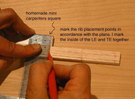
I don’t believe you need to build over a plan, though you can slip the plan under the glass if you like. Instead carefully mark the joint location of the ribs on the LE and TE as per the plans. I mark them together if possible with a red Flair and a homemade square.
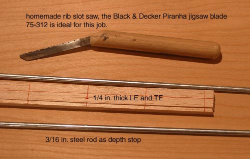
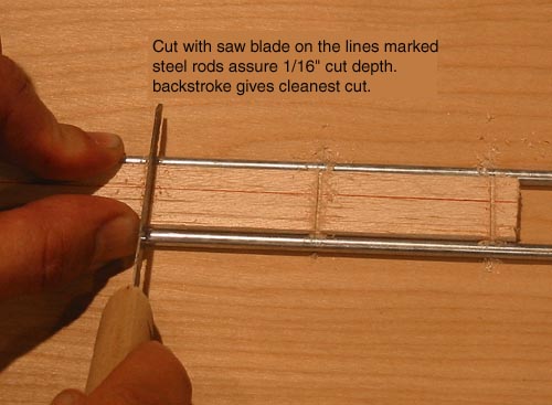
Once marked, I cut a 1/16” deep slot on each line. I use a 3/16” steel rod on either side of the wood to act as a depth stop. A Black & Decker Piranha jigsaw blade (75-312) attached to an offset hardwood dowel handle is my saw of choice for this task. It cuts clean and quick. The slot it makes allows for a snug secure fit of the 1/16” thick ribs. I’m sure other saw blades could work as well.
I should note that the wing tip ribs may need special attention. I usual make the LE and TE about an1/8” to 1/4” longer that need be to give ample footing for the tip rib slot. After the assembly and gluing is complete I trim off the excess with a razor saw. If you need a double thick center rib carefully widen the slot by an extra cut or try holding two blades together when making the cut.
Next, I mark a center point on the leading edge of each rib. This will aid center alignment of the ribs in the LE slots. I don’t have to worry about the TE, as it is the same thickness as the trailing edge of the rib making it easy to center.
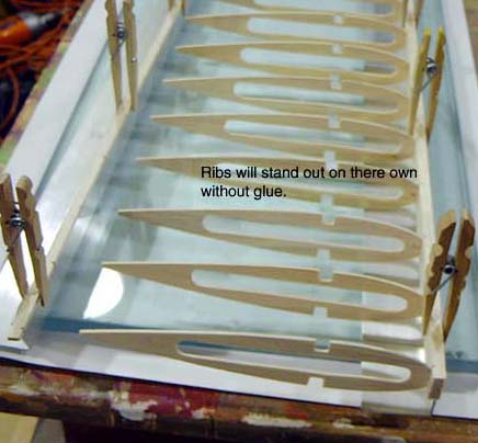
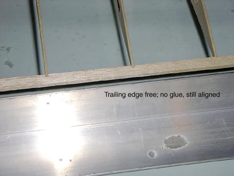
To demonstrate the strength of the slot’s hold I have assembled the wing without the jig or glue. As you can see it will support its own weight yet can be easily slipped apart.
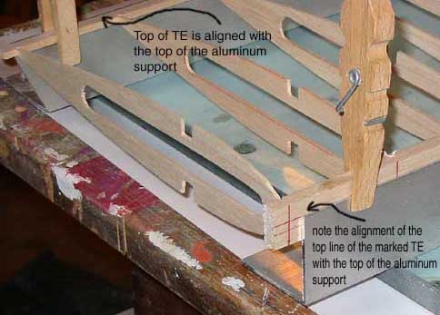
To construct the wing in the jig goes something like this. Use the reversed cloths pins to clamp the LE and TE to their aluminum supports. The upper side of the TE should be even/flush with the top of the support along its entire length. The LE is aligned so that the upper red line on the front of the LE (remember the two lines represent the thickness of the TE) is even/flush with the top of the support along its entire length. This assures the horizontal centering of the LE & TE. The LE support is usually fixed in place (taped) before adding the ribs.
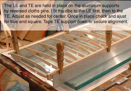
Carefully insert each; rib in order, in the slots along the LE. Aligning the center mark on the rib with the centerline on the inside of the LE. I Keep the TE support close but not quite touching the back edge of the ribs so I can assure the horizontal rib alignment is close before actually pressing them into the TE slots. The ribs should stand out from the LE held in place by the fit of the slot, not glue.
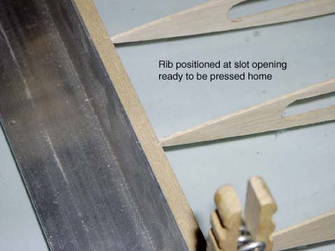
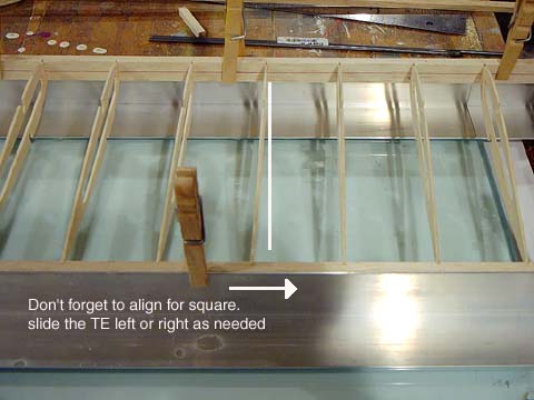
Slide the TE support forward to touch the back ends of the ribs. Gently position each rib at the opening of its assigned TE slot, check all alignments. Carefully push each rib in order into its TE slot as far as it will go (1/16”). You will move the TE support a bit as you go. When all the ribs are seated in their slots front and back, recheck all alignments. Don’t forget to check the wing for square, if need be slide the TE support left or right to align the ribs and the center of the TE and the LE. I use a drafting triangle for this task. The wing should be straight and true at this point. When you’re happy with the alignment fix (tape) the TE support in position. (I have been able to remove the TE clamps at this time and have the wing remain aligned with the TE support) With everything aligned square and true I put a drop of CA glue on each joint. The top and bottom spars are now added. I do the top spar first. Check alignment and seating in the rib notches before CA glue is applied. Next I do the bottom spar. It is often easier to flip the wing top for bottom in the jig to access and align the spar in the notches.
From here on it’s pretty much down hill. I remove the wing from the jig and move the TE support in about 1/4” closer to the LE support. This will allow me to rest the wing on top of the aluminum supports (it should make contact all along the length of the LE and TE) allowing me to keep an eye on alignment while the bell crank mount, and the leading and trailing edge sheeting is added.
I believe this covers the major steps of using the jig. If you’re experienced in building you should be good from here on. Again I should emphasize the importance of using straight wood so no stresses are built into the wing. At the very least arrange any slight bows or curves so they cancel each others effect. I.e. if both spars are bowed, align them so they bow in opposite directions. If they are aligned in the same direction, the bow is amplified and can curve the entire wing. I hope this has been helpful and not to long.
Good Luck.
Bob;)
This article was created by Mike Nelson. Some of the stuff came from the Stuka Stunt Forum
Go back to Mike Nelsons Home Page